
User Manual
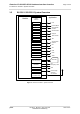
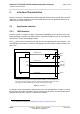
Table Of Contents
- Contents
- Tables
- Figures
- 1 Introduction
- 2 Interface Characteristics
- 2.1 Application Interface
- 2.2 RF Antenna Interface
- 2.3 Sample Application
- 3 Operating Characteristics
- 4 Mechanical Dimensions, Mounting and Packaging
- 5 Regulatory and Type Approval Information
- 6 Document Information
- 7 Appendix

Cinterion
®
ELS31-V/ELS51-V Hardware Interface Overview
Figures
35
ELS31-V_ELS51-V_HIO_v00.502 2015-12-07
Confidential / Preliminary
Page 1 of 35
Figures
Figure 1: ELS31-V / ELS51-V system overview.............................................................. 5
Figure 2: USB circuit ....................................................................................................... 6
Figure 3: Serial interface ASC0....................................................................................... 7
Figure 4: Serial interface ASC1....................................................................................... 8
Figure 5: External UICC/SIM/USIM card holder circuit ................................................. 10
Figure 6: Schematic diagram of ELS31-V / ELS51-V sample application..................... 17
Figure 7: ELS31-V– top and bottom view...................................................................... 20
Figure 8: Dimensions of ELS31-V / ELS51-V (all dimensions in mm)........................... 21
Figure 9: Dimensions of ELS31-V / ELS51-V (all dimensions in mm) - bottom view .... 21
Figure 10: Reference equipment for Type Approval ....................................................... 25