
User Manual
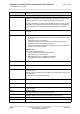
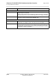
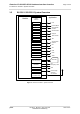
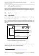
Table Of Contents
- Contents
- Tables
- Figures
- 1 Introduction
- 2 Interface Characteristics
- 2.1 Application Interface
- 2.2 RF Antenna Interface
- 2.3 Sample Application
- 3 Operating Characteristics
- 4 Mechanical Dimensions, Mounting and Packaging
- 5 Regulatory and Type Approval Information
- 6 Document Information
- 7 Appendix

Cinterion
®
ELS31-V/ELS51-V Hardware Interface Overview
1.1 Key Features at a Glance
5
ELS31-V_ELS51-V_HIO_v00.502 2015-12-07
Confidential / Preliminary
Page 3 of 35
Interfaces
Module interface Surface mount device with solderable connection pads (SMT application
interface). Land grid array (LGA) technology ensures high solder joint reli-
ability and allows the use of an optional module mounting socket.
For more information on how to integrate SMT modules see also [4]. This
application note comprises chapters on module mounting and application
layout issues as well as on SMT application development equipment.
USB USB 2.0 High Speed (480Mbit/s) device interface, Full Speed (12Mbit/s)
compliant
2 serial interfaces ASC0:
• 8-wire modem interface with status and control lines, unbalanced, asyn-
chronous
• Default baud rate: 115,200 baud
• Adjustable baud rates: 1,200 to 921,600, no autobauding support
• Supports RTS0/CTS0 hardware flow control.
• indication of incoming data/SMS on RING0 (can be used to wake up
host from power down modes)
ELS51-V only:
ASC1 (shared with GPIO lines):
• 4-wire, unbalanced asynchronous interface
• Default baud rate: 115,200 baud
• Adjustable baud rates: 1,200bps to 921,600bps
• Supports RTS1/CTS1 hardware flow control
UICC interface Supported SIM/USIM cards: 3V, 1.8V
Embedded UICC Module is prepared for an embedded UICC
GPIO interface 20 pads of the application interface programmable as GPIO pads (17) or
GPO pads (3):
GP(I)Os can be configured as COUNTER, FST_SHDN, ASC0, ASC1, and
SPI signal lines
Programming is done via AT commands
I
2
C interface Supports I
2
C serial interface
SPI interface Supports SPI interface
SDIO ELS51-V only:
4 wire interface.
HSIC ELS51-V only:
High Speed Interchip Communication interface.
ADC
Analog-to-Digital Converter with one unbalanced analog input.
Digitial audio interface Hardware prepared for future use.
Antenna interface pads 50 LTE main antenna, 50LTE diversity antenna
Feature Implementation