
User Manual
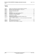
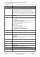
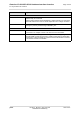
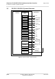
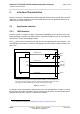
Table Of Contents
- Contents
- Tables
- Figures
- 1 Introduction
- 2 Interface Characteristics
- 2.1 Application Interface
- 2.2 RF Antenna Interface
- 2.3 Sample Application
- 3 Operating Characteristics
- 4 Mechanical Dimensions, Mounting and Packaging
- 5 Regulatory and Type Approval Information
- 6 Document Information
- 7 Appendix

Cinterion
®
ELS31-V/ELS51-V Hardware Interface Overview
1.1 Key Features at a Glance
5
ELS31-V_ELS51-V_HIO_v00.502 2015-12-07
Confidential / Preliminary
Page 4 of 35
Power on/off, Reset
Power on/off Switch-on by hardware signal ON
Switch-off by AT command
Switch off by hardware signal GPIO4/FST_SHDN instead of AT command
Automatic switch-off in case of critical temperature and voltage conditions
Reset Orderly shutdown and reset by AT command
Emergency reset by hardware signal EMERG_RST
Evaluation kit
Evaluation module ELS31-V / ELS51-V module soldered onto a dedicated PCB that can be
connected to an adapter in order to be mounted onto the DSB75.
DSB75 DSB75 Development Support Board designed to test and type approve
Gemalto M2M modules and provide a sample configuration for application
engineering. A special adapter is required to connect the ELS31-V / ELS51-
V evaluation module to the DSB75.
Feature Implementation