HC25 Siemens Cellular Engine Version: DocId: 00.220 HC25_HO_v00.
HC25 Hardware Interface Overview s 2 Document Name: HC25 Hardware Interface Overview Version: 00.220 Date: 2007-03-20 DocId: HC25_HO_v00.220 Status: Confidential / Preliminary Supported Products: HC25 General Notes Product is deemed accepted by Recipient and is provided without interface to Recipient´s products. The Product constitutes pre-release version and code and may be changed substantially before commercial release.
HC25 Hardware Interface Overview Contents 39 s Contents 1 Introduction ................................................................................................................. 6 1.1 Related Documents ........................................................................................... 6 1.2 Terms and Abbreviations ................................................................................... 6 1.3 Regulatory and Type Approval Information ...............................................
HC25 Hardware Interface Overview Tables 4 s Tables Table 1: Table 2: Table 3: Table 4: Table 5: Table 6: Table 7: Table 8: Table 9: Table 10: Table 11: Table 12: Table 13: Table 14: Table 15: Table 16: Table 17: Table 18: Table 19: Directives ......................................................................................................... 9 Standards of North American type approval .................................................... 9 Standards of European type approval..........................
HC25 Hardware Interface Overview Figures 5 s Figures Figure 1: Figure 2: Figure 3: Figure 4: Figure 5: Figure 6: Figure 7: Figure 8: Figure 9: Restricted area around antenna pad (side and bottom view) ......................... 18 Mechanical dimensions of U.FL-R-SMT connector......................................... 19 U.FL-R-SMT connector with U.FL-LP-040 plug .............................................. 20 U.FL-R-SMT connector with U.FL-LP-066 plug ..............................................
HC25 Hardware Interface Overview 1 Introduction 12 1 s Introduction This document describes the hardware of the Siemens HC25 module that connects to the cellular device application and the air interface. It helps you quickly retrieve interface specifications, electrical and mechanical details and information on the requirements to be considered for integrating further components. 1.1 [1] [2] Related Documents HC25 AT Command Set 00.220 HC25 Release Notes 00.220 1.
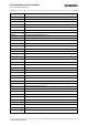
HC25 Hardware Interface Overview 1.2 Terms and Abbreviations 12 s Abbreviation Description EMC Electromagnetic Compatibility ERP Effective Radiated Power ESD Electrostatic Discharge ETS European Telecommunication Standard ETSI European Telecommunications Standards Institute FCC Federal Communications Commission (U.S.
HC25 Hardware Interface Overview 1.2 Terms and Abbreviations 12 Abbreviation Description RACH Random Access Channel RF Radio Frequency RTC Real Time Clock Rx Receive Direction SAR Specific Absorption Rate SELV Safety Extra Low Voltage SIM Subscriber Identification Module SLIC Subscriber Line Interface Circuit SMS Short Message Service SRAM Static Random Access Memory SRB Signalling Radio Bearer TA Terminal adapter (e.g.
HC25 Hardware Interface Overview 1.3 Regulatory and Type Approval Information 12 1.3 Regulatory and Type Approval Information 1.3.1 Directives and Standards s HC25 has been designed to comply with the directives and standards listed below. Table 1: Directives 99/05/EC Directive of the European Parliament and of the council of 9 March 1999 on radio equipment and telecommunications terminal equipment and the mutual recognition of their conformity (in short referred to as R&TTE Directive 1999/5/EC).
HC25 Hardware Interface Overview 1.3 Regulatory and Type Approval Information 12 s Table 3: Standards of European type approval EN 301 489-24 V1.2.1 Electromagnetic compatibility and Radio Spectrum Matters (ERM); Electromagnetic Compatibility (EMC) standard for radio equipment and services; Part 24: Specific conditions for IMT-2000 CDMA Direct Spread (UTRA) for Mobile and portable (UE) radio and ancillary equipment EN 301 908-01 V2.2.
HC25 Hardware Interface Overview 1.4 SAR requirements specific to portable mobiles 12 1.4 s SAR requirements specific to portable mobiles Mobile phones, PDAs or other portable transmitters and receivers incorporating a GSM module must be in accordance with the guidelines for human exposure to radio frequency energy. This requires the Specific Absorption Rate (SAR) of portable HC25 based applications to be evaluated and approved for compliance with national and/or international regulations.
HC25 Hardware Interface Overview 1.5 Safety Precautions 12 1.5 s Safety Precautions The following safety precautions must be observed during all phases of the operation, usage, service or repair of any cellular terminal or mobile incorporating HC25. Manufacturers of the cellular terminal are advised to convey the following safety information to users and operating personnel and to incorporate these guidelines into all manuals supplied with the product.
HC25 Hardware Interface Overview 2 Product Concept 15 2 Product Concept 2.
HC25 Hardware Interface Overview 2.
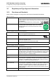
HC25 Hardware Interface Overview 2.1 Key Features at a Glance 15 Feature s Implementation Interfaces USB Supports a USB 2.0 Full Speed (12Mbit/s) device interface. Wakeup Control Signal pin to wake up an inactive USB Host into an active state. Status Signal pins to indicate network connectivity status. Audio 1 analog interface UICC interface Supported chip cards: SIM / UICC 3V, 1.8V Antenna 50Ohms. External antenna can be connected via antenna connector or antenna pad (spring contact).
HC25 Hardware Interface Overview 3 Application Interface 16 3 s Application Interface HC25 is equipped with a 50-pin board-to-board connector that connects to the external application and incorporates several sub-interfaces: power supply, USB interface, UICC/SIM interface, analog audio interface, as well as various status and control lines (see also Chapter 2). 3.1 Operating Modes The table below briefly summarizes the various operating modes referred to in the following chapters.
s HC25 Hardware Interface Overview 4 Antenna Interface 22 4 Antenna Interface The RF interface has an impedance of 50Ω. HC25 is capable of sustaining a total mismatch at the antenna connector or pad without any damage, even when transmitting at maximum RF power. The external antenna must be matched properly to achieve best performance regarding radiated power, DC-power consumption, modulation accuracy and harmonic suppression.
HC25 Hardware Interface Overview 4.2 Antenna Pad 22 s No matter which option you choose, ensure that the antenna pad does not come into contact with the holding device or any other components of the host application. It needs to be surrounded by a restricted area filled with air, which must also be reserved 1.4mm in height. Figure 1: Restricted area around antenna pad (side and bottom view) 4.2 Antenna Pad The antenna can be attached via contact springs.
s HC25 Hardware Interface Overview 4.3 Antenna Connector 22 4.3 Antenna Connector HC25 uses an ultra-miniature SMT antenna connector supplied from Hirose Ltd. The product name is: • U.FL-R-SMT Figure 2: Mechanical dimensions of U.FL-R-SMT connector Table 7: Product specifications of U.FL-R-SMT connector Item Specification Conditions Nominal impedance 50Ω Operating temp:-40°C to + 90°C Operating humidity: max.
s HC25 Hardware Interface Overview 4.3 Antenna Connector 22 Table 7: Product specifications of U.FL-R-SMT connector Item Specification Conditions Temperature cycle No damage, cracks and looseness of parts. Contact resistance: Center 25mΩ Outside 15mΩ Temperature: +40°C → 5 to 35°C → +90°C → 5 to 35°C Time: 30min → within 5min → 30min within 5min Salt spray test No excessive corrosion 48 hours continuous exposure to 5% salt water Table 8: Material and finish of U.
HC25 Hardware Interface Overview 4.3 Antenna Connector 22 s In addition to the connectors illustrated above, the U.FL-LP-(V)-040(01) version is offered as an extremely space saving solution. This plug is intended for use with extra fine cable (up to Ø 0.81mm) and minimizes the mating height to 2mm. See Figure 5 which shows the Hirose datasheet. Figure 5: Specifications of U.FL-LP-(V)-040(01) plug HC25_HO_v00.
s HC25 Hardware Interface Overview 4.3 Antenna Connector 22 Table 9: Ordering information for Hirose U.FL Series Item Part number HRS number Connector on HC25 U.FL-R-SMT CL331-0471-0-10 Right-angle plug shell for Ø 0.81mm cable U.FL-LP-040 CL331-0451-2 Right-angle plug for Ø 0.81mm cable U.FL-LP(V)-040 (01) CL331-053-8-01 Right-angle plug for Ø 1.13mm cable U.FL-LP-068 CL331-0452-5 Right-angle plug for Ø 1.32mm cable U.FL-LP-066 CL331-0452-5 Extraction jig E.
s HC25 Hardware Interface Overview 5 Electrical, Reliability and Radio Characteristics 26 5 Electrical, Reliability and Radio Characteristics 5.1 Absolute Maximum Ratings The absolute maximum ratings stated in Table 10 are stress ratings under any conditions. Stresses beyond any of these limits will cause permanent damage to HC25. Table 10: Absolute maximum ratings Parameter Min Max Unit Supply voltage BATT+ -0.3 4.5 V Voltage at digital pins in POWER DOWN mode -0.3 0.
s HC25 Hardware Interface Overview 5.2 Operating Temperatures 26 5.2 Operating Temperatures The values stated below are in compliance with GSM recommendation TS 51.010-01. Table 11: Board temperature Parameter Min Typ Max Unit Operating temperature range -20 +25 +85 °C Automatic shutdown1 Temperature measured on HC25 board < -30 --- >+85 °C 1. Due to temperature measurement uncertainty, a tolerance on the stated shutdown thresholds may occur.
s HC25 Hardware Interface Overview 5.3 Storage Conditions 26 5.3 Storage Conditions The conditions stated below are only valid for modules in their original packed state in weather protected, non-temperature-controlled storage locations. Normal storage time under these conditions is 12 months maximum. Table 14: Storage conditions Type Condition Unit Reference Air temperature: Low High -40 +85 °C ETS 300 019-2-1: T1.2, IEC 68-2-1 Ab ETS 300 019-2-1: T1.
HC25 Hardware Interface Overview 5.4 Reliability Characteristics 26 5.4 s Reliability Characteristics The test conditions stated below are an extract of the complete test specifications. Table 15: Summary of reliability test conditions Type of test Conditions Standard Vibration Frequency range: 10-20Hz; acceleration: 3.
s HC25 Hardware Interface Overview 6 Mechanics 30 6 Mechanics 6.1 Mechanical Dimensions of HC25 Length:50.00mm Width: 34.00mm Height: 4.5mm RF Antenna Connector Ground Pin 1 Pin 25 Pin 50 Pin 26 Ground (for Heat Sink) Ground Figure 6: HC25 – Top and bottom view HC25_HO_v00.
HC25 Hardware Interface Overview 6.1 Mechanical Dimensions of HC25 30 s Figure 7: Dimensions of HC25 (all dimensions in mm) HC25_HO_v00.
HC25 Hardware Interface Overview 6.2 Mounting HC25 to the Application Platform 30 6.2 s Mounting HC25 to the Application Platform There are many ways to properly install HC25 in the host device. An efficient approach is to mount the HC25 PCB to a frame, plate, rack or chassis. Fasteners can be M2 screws plus suitable washers, circuit board spacers, or customized screws, clamps, or brackets. In addition, the board-to-board connection can also be utilized to achieve better support.
HC25 Hardware Interface Overview 6.3 Board-to-Board Application Connector 30 s A recommended corresponding board-to-board connector series for external applications is: Supplier: Hirose ( www.hirose.com ) Type: DF12x-50DP-0.5V (SlimStack Header) Height: 3.0 – 5.0 mm For Hirose sales contacts see Chapter 8. Note: There is no inverse polarity protection for the board-to-board connector. It is therefore very important that the board-to-board connector is connected correctly to the host application, i.e.
HC25 Hardware Interface Overview 7 Reference Approval 32 7 Reference Approval 7.1 Reference Equipment for Type Approval s The Siemens reference setup submitted to type approve HC25 consists of the following components: • Siemens HC25 cellular engine • Development Support Box DSB75 and HC15/HC25-DSB75-Adapter for mounting the HC25 module • SIM card reader integrated on DSB75 • U.FL-LP antenna cable • Handset type Votronic HH-SI-30.3/V1.
HC25 Hardware Interface Overview 7.2 Compliance with FCC Rules and Regulations 32 7.2 s Compliance with FCC Rules and Regulations The Equipment Authorization Certification for the Siemens reference application described in Section 7.
s HC25 Hardware Interface Overview 8 Appendix 39 8 Appendix 8.
HC25 Hardware Interface Overview 8.1 List of Parts and Accessories 39 s Table 18: Molex sales contacts (subject to change) Molex For further information please click: http://www.molex.com Molex Deutschland GmbH Felix-Wankel-Str. 11 4078 Heilbronn-Biberach Germany Phone: +49-7066-9555 0 Fax: +49-7066-9555 29 Mail: mxgermany@molex.com American Headquarters Lisle, Illinois 60532 U.S.A. Phone: +1-800-78MOLEX Fax: +1-630-969-1352 Molex China Distributors Beijing, Room 1319, Tower B, COFCO Plaza No.
HC25 Hardware Interface Overview 8.2 Fasteners and Fixings for Electronic Equipment 39 8.2 s Fasteners and Fixings for Electronic Equipment This section provides a list of suppliers and manufacturers offering fasteners and fixings for electronic equipment and PCB mounting. The content of this section is designed to offer basic guidance to various mounting solutions with no warranty on the accuracy and sufficiency of the information supplied.
HC25 Hardware Interface Overview 8.2 Fasteners and Fixings for Electronic Equipment 39 Article number: 07.51.403 Insulating Spacer for M2 Self-gripping1 Length 3.0mm Material Polyamide 6.6 Surface Black Internal diameter 2.2mm External diameter 4.0mm Flammability rating UL94-HB 1. s 2 spacers are delivered with DSB75 Support Board Article number: 05.11.209 Threaded Stud M2.5 - M2 Type E / External thread at both ends Length 3.
HC25 Hardware Interface Overview 8.2 Fasteners and Fixings for Electronic Equipment 39 Article number: 01.14.131 Screw M21 DIN 84 - ISO 1207 Length 8.0mm Material Steel 4.8 Surface Zinced A2K Thread M2 Head diameter D = 3.8mm Head height 1.30mm Type Slotted cheese head screw 1. s 2 screws are delivered with DSB75 Support Board Article number: 01.14.141 Screw M2 DIN 84 - ISO 1207 Length 10.0mm Material Steel 4.8 Surface Zinced A2K Thread M2 Head diameter D = 3.
s HC25 Hardware Interface Overview 8.3 Mounting Advice Sheet 39 Article number: 02.10.011 Hexagon Nut1 DIN 934 - ISO 4032 Material Steel 4.8 Surface Zinced A2K Thread M2 Wrench size / Ø 4 Thickness / L 1.6mm Type Nut DIN/UNC, DIN934 1. 8.3 2 nuts are delivered with DSB75 Support Board Mounting Advice Sheet To prevent mechanical damage, be careful not to force, bend or twist the module. Be sure it is positioned flat against the host device.
HC25 Hardware Interface Overview 8.3 Mounting Advice Sheet 39 HC25_HO_v00.