
User's Guide

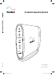
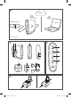


Table Of Contents

2
RCM at a glance
Refer to illustration B.
1.
Stand
6.
Wall mount
2.
Wall mounting socket
7.
Power Supply Unit (PSU)
3.
Indicator panel
8.
Plug blade attachments
4.
Micro-USB port
9.
USB cable (not shown)
5.
Power inlet
Indicators
Refer to illustration C.
RCM provides indication of the current operating state. When the Power and Vent. Input indicators
illuminate and you have network reception, RCM is ready to use.
Indicator Status
1 Power – Green
Indicates whether RCM is powered on.
On: The power is on.
Off: The power is off.
2 Vent. Input – Blue
Indicates whether RCM is connected to the powered-on
ventilation device.
On: Connected to the ventilation device.
Off: Disconnected from the ventilation device.
Blinking: Establishing connection to the ventilation device.
3 Signal – Blue
Indicates connectivity to the cellular network and the signal
strength.
On: Connected to the cellular network. The signal strength
is indicated by the number of blue dots (more dots mean a
stronger signal).
Off: No cellular network detected.
4 Error – Yellow
Indicates whether RCM has an error.
On: An error has occurred.
Off: No error
Note: The Vent. Input and Signal indicators will dim in 5 minutes and will return to full brightness
when RCM is connected to the ventilation device or powered on again.
Assembling the PSU
Refer to illustration D.
1. Insert the plug blade attachment suitable for your region into the PSU.
2. To remove the plug blade attachment from the PSU, press the button under the arrow and slide
it out.
CAUTION
• Do not leave the plug blade attachment in a power outlet alone.
• Do not plug the PSU upside down into a power outlet. Ensure that the power cord extends
downward.