
Automobile Parts User Manual

8
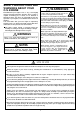
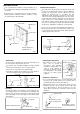
It is essential that the firewall is strong and rigid (e.g. at
least 15mm thick) and firmly integrated with the structure of
the aircraft.
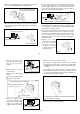
INSTALLATION
In the interests of scale appearance, the engine should be
installed with the carburetor below the crankcase so that
the exhaust pipes point downwards.
Centre mark
M5 Blind nut
Centre mark
Firewall
M5x25 screw
5 Lock washer
At least 15mm (0.6")
rigid hard wood
Fig. 1
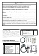
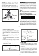
Needle-valve extension
The needle-valve with this engine is designed to incorporate
an extension so that, when the engine is enclosed within the
fuselage, the needle-valve may be adjusted from the
outside. An L-shaped rod, of 1.6-1.8mm dia. and
appropriate length, should be inserted into the needle's
centre hole and secured by tightening the set-screw in the
needle-valve knob with the small Allen key provided. For
longer extension, it is recommended to use the extension
cable with the engine, together with the knob and support
hook also. For this purpose, Needle Valve Extension Cable
Set (Code No. 72200080) is available as an optional part.
Do not use an excessively long unsupported extension as
this may vibrate and cause the needle-valve setting to vary
or even damage the needle-valve thread. Always provide a
suitable support at the outer end.
Fig. 2
Set-screw
Set-screw
Hook
Knob
Cable
Needle
9
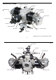
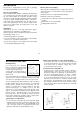
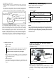
Choke valve
The choke valve operating lever can be located rught or left
by reversing the hexagon nut nd cap screw.
Unscrew the cap screw while holding the hexagon nut with
6mm wrench, and re-fit the lever to required location.
If the rod is too long, reduce it to required length.
A needlessly lengthy rod may vibrete. The rod should be as
short as possible or have its outer end supported.
Fig. 3
Set-screw
Choke lever
Hex. nut
Cap screw
Choke rubber pad
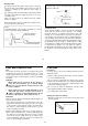
Fuel inlet
The fuel inlet nipple on the carburetor can be adjusted to the
most suitable position for connecting to the fuel delivery tube
from the tank. Slacken the needle-valve holder with the 8mm
wrench provided, reset the inlet nipple at the required angle
and re-tighten.
Fig. 4
Fuel inlet
Needle-valve
Slacken with 8mm wrench
Exhaust pipe adjustment
The direction of the exhaust
pipes may be altered in
accordance with individual
installation requirements. The
angle is easily adjusted by
loosening the nut that secures
the exhaust pipe to the cylinder
head. Use the 12mm wrench
supplied.
Fig. 5
12mm wrench
Loosen
Tighten
Lock nut
Exhaust pipe
Carburetor cleanliness
It is recommended that the fuel is passed through a filter
when the tank is filled and that a good in-line filter is
installed between the fuel tank and carburetor.
Occasionally remove the needle-valve holder from the
carburetor and rinse out the locaions shown in Fig. 6 and
Fig. 7 with methanol or fuel. Be careful not to lose the
gasket when removing the needle-valve holder from the
carburetor.
Fig. 6
Fig. 7
Squeeze bottle
Dirt and fibrous matter
mostly accumulate here.
Dirt and fibrous matter
mostly accumulate here.
Needle-valve holder