
Installation Instructions
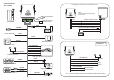

YELLOW
+30
Ignition Key
Direction Indicator Ligths
RED
BLUE
Self-Powered Sirene
GREEN-BROWN
Door Pin Switch
GREEN
Boot/Bonnet Pin Switch
EARTH
Positive allarm ON
YELLOW-BROWN
RED-BROWN
YELLOW-GREY
RED-GREY
Refer to central door locking diagrams
YELLOW-BLUE
RED-BLUE
BLACK
Supplementary Siren
WHITE
GREY
Engine immobilisation
8A
MAX !
10A
12 VOLT
+
-
Battery
BROWN
PINK
ORANGE
ORANGE
5A
5A
Art. 4008GE
1160
FITTING DIAGRAM
ART. 1160RSD
1160
1160
3 way connector for
ultrasonic sensor
YELLOW-BLACK
Common for
Supplementary Siren
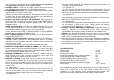
Fitting diagram 1160 central unit with 5025 siren.
BLACK marked RB or Red-White
BLACK marked MB or White-Brown
15A
BLACK marked R or Red
BLACK marked L or Blue
BLACK marked Z or Violet
BLACK marked Z or Violet
NOTE :
The black wires has the identification
mark in the end.
CLAMP
+
_
BATTERY
12VOLT
GREY
WHITE
RED
BLUE
EX : ALFA,FIAT,FORD,LANCIA,OPEL,PEUGEOT,SAAB,VW POLO(95>).
YELLOW-BLUE
RED-BLUE
YELLOW-GREY
RED-GREY
YELLOW-BROWN
RED-BROWN
+30
+30
Diagram N° 2
Common
Open
Close
Do not connect
Do not connect