
Operation Manual
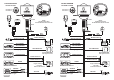


FITTING DIAGRAM
ref.7203 et 7202
FITTING DIAGRAM
ref.7203E et 7202E
File:centrale-UK CDR File:centrale-UK CDR
YELLOW YELLOW
+30 +30
Ignition Key Ignition Key
GREEN-BROWN GREEN-BROWN
Door Pin Switch Door Pin Switch
GREEN GREEN
Boot/Bonnet Pin Switches Boot/Bonnet Pin Switches
BLACK marked M BLACK marked M
Red Red
Black Black
YELLOW-GREY YELLOW-GREY
RED-GREY RED-GREY
Refer to central door locking diagrams Refer to central door locking diagrams
Direction indicator lights Direction indicator lights
ORANGE ORANGE
ORANGE ORANGE
BLACK marked H BLACK marked H
BLACK marked H BLACK marked H
Engine immobilisation.
Fuel pump.
Solenoid valve-diesel.
Engine immobilisation.
Fuel pump.
Solenoid valve-diesel.
8A
MAX !
8A
MAX !
EARTH EARTH
YELLOW-BLACK YELLOW-BLACK
Supplementary Siren
with negative control
Supplementary Siren
with negative control
15A 15A
BLACK marked R BLACK marked R
Battery Battery
12 VOLT 12 VOLT
+ +
--
Aerial Aerial
5A 5A
5A 5A
Push-Button 2 Push-Button 2
Push-Button 1 Push-Button 1
NOTE :
The Black wires have
the identification mark in the end.
NOTE :
The Black wires have
the identification mark in the end.
Pink
Pink
Brown
Brown
Green/black
Green/black
+ +- -
Ultrasonic module Ultrasonic module
YELLOW-RED YELLOW-RED
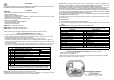
CLAMP CLAMP
CLAMP CLAMP
CLAMP CLAMP
7059 7059
5123 5123
+
-
ON
21 3456
ON
21 3456