
User Manual


7
3 Installation
1. Mount the Access Point firmly to the wall on the position that is determined during the site survey. A drill model is supplied
as a separate sheet with this manual.
2. Make sure the antennas are in a vertical position (if not, rotate over 90 degrees).
3. Insert the power connector.
4. Attach the UTP Ethernet cable to the Access Point.
5. Switch on the Access Point.
At the front of the Access Point you will see three LEDs.
If all goes well, the middle LED (power) is green and the leftmost (WLAN) and rightmost (wired network) LEDs flash whenever
there is traffic on the respective networks, which is at least ten times per second for the wireless LAN because of so-called
‘beacons’.
The Access Point automatically selects the medium attached. When the cable network is detected, the network LED will turn
green.
You can reset the Access Point’s settings to factory defaults by pushing a paperclip in the little hole next to the power switch.
The sequence of the ACT is on, and keeps holding until the LED is being turned off.
When you push a paperclip in the reset hole while the Access Point is switched on, only the lock set by APManager (Par 4.5) is
deactivated.
This device provides three operational mode of the Access Point available.
Access Point: This mode provides access for wireless stations to wired LANs and from wired LANs to wireless stations.
AP Client: The function is same as normal wireless NIC card.
Wireless Bridge: This mode allows the connection of one or more remote LANs with a central LAN.
3-1 Install Procedure
Step 1. Plug in the power supply. The power LED will turn on to indicate power
operation.
User may connect the Ap/ AP client/Wireless Bridge to a hub or particular device for different purpose use.
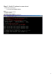
Step 2. Setting the IP Address of the Access Point
This procedure can be done either through the Ethernet port by using a combination of Arp / Ping commands and the
SNMP Manager.