
User Manual

BW1251 Nov 15, 2006
Browan Page 12 of 72
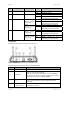
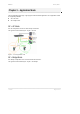
Item LED Color Status Indication
On BW1251 is active/working 1 Power Green
Blink BW1251 is booting
On BW1251 Ethernet Port Link Active 2 LAN Green
Blink
BW1251 Ethernet Port is
Transmitting and Receiving data
On BW1251 WLAN1 RF card Active Green
(802.11g module
is functional)
Blink
BW1251 WLAN1 RF card is
Transmitting and Receiving data
On BW1251 WLAN1 RF card Active
3 Wireless1
Amber
(802.11a module
is functional)
Blink
BW1251 WLAN1 RF card is
Transmitting and Receiving data
On BW1251 WLAN2 RF card Active Green
(802.11g module
is functional)
Blink BW1251 WLAN2 RF card is
Transmitting and Receiving data
On BW1251 WLAN2 RF card Active
4 Wireless2
Amber
(802.11a module
is functional)
Blink
BW1251 WLAN2 RF card is
Transmitting and Receiving data
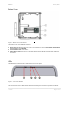
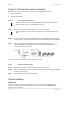
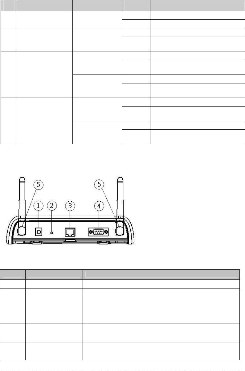
Connectors
The BW1251 has several connectors on the rear panel:
Figure 4 – Connectors
Descriptions of the connectors are given in the following table:
Item Connector Description
1
Power Jack For DC12V power supply
2
Reset button
Reboot or reset to factory defaults.
Press the reset bottom for less than 5 seconds to reboot the
Access Point. Press the reset bottom for more than 5 seconds
to reset the Access Point to factory defaults
3
LAN
Connect to the RJ45 port of your laptop for configuration or
connect to the PoE device for power supply and network
connection
4
Console For console connection
5
R-TNC Connector For Antenna connection