4020210 Rev A DDR2200-CL Series Residential Gateway Installation and Operation Guide
Please Read Important Please read this entire guide. If this guide provides installation or operation instructions, give particular attention to all safety statements included in this guide.
Notices Trademark Acknowledgments Cisco, Cisco Systems, the Cisco logo, and the Cisco Systems logo are registered trademarks or trademarks of Cisco Systems, Inc. and/or its affiliates in the U.S. and certain other countries. HPNA is a trademark of the Home Phoneline Networking Alliance. All other trademarks mentioned in this document are the property of their respective owners. Publication Disclaimer Cisco Systems, Inc. assumes no responsibility for errors or omissions that may appear in this publication.
Notice to Installers The servicing instructions in this notice are for use by qualified service personnel only. To reduce the risk of electric shock, do not perform any servicing other than that contained in the operating instructions, unless you are qualified to do so. Notice à l’attention des installateurs de réseaux câblés Les instructions relatives aux interventions d’entretien, fournies dans la présente notice, s’adressent exclusivement au personnel technique qualifié.
Mitteilung für CATV-Techniker Die in dieser Mitteilung aufgeführten Wartungsanweisungen sind ausschließlich für qualifiziertes Fachpersonal bestimmt. Um die Gefahr eines elektrischen Schlags zu reduzieren, sollten Sie keine Wartungsarbeiten durchführen, die nicht ausdrücklich in der Bedienungsanleitung aufgeführt sind, außer Sie sind zur Durchführung solcher Arbeiten qualifiziert.
Contents IMPORTANT SAFETY INSTRUCTIONS United States FCC Compliance vii x CE Compliance xiii About This Guide xvii Chapter 1 Introducing the DDR2200 Series Residential Gateway 1 Benefits and Features .............................................................................................................. 2 What's On the Front Panel? .................................................................................................... 4 What's On the Back Panel? .....................................
Contents Updating Software................................................................................................................. 37 Settings Backup ...................................................................................................................... 38 Update Settings ...................................................................................................................... 40 Customer Configuration File ................................................................
Contents Chapter 6 Security Configuration 141 MAC Filtering Setup ........................................................................................................... 142 Incoming IP Filtering........................................................................................................... 148 Outgoing IP Filtering........................................................................................................... 154 Parental Control Setup - Filtering Function .....................
IMPORTANT SAFETY INSTRUCTIONS IMPORTANT SAFETY INSTRUCTIONS 1) Read these instructions. 2) Keep these instructions. 3) Heed all warnings. 4) Follow all instructions. 5) Do not use this apparatus near water. 6) Clean only with dry cloth. 7) Do not block any ventilation openings. Install in accordance with the manufacturer's instructions. 8) Do not install near any heat sources such as radiators, heat registers, stoves, or other apparatus (including amplifiers) that produce heat.
IMPORTANT SAFETY INSTRUCTIONS Protect the Product from Lightning In addition to disconnecting the AC power from the wall outlet, disconnect the signal inputs. Verify the Power Source from the On/Off Power Light When the on/off power light is not illuminated, the apparatus may still be connected to the power source. The light may go out when the apparatus is turned off, regardless of whether it is still plugged into an AC power source.
IMPORTANT SAFETY INSTRUCTIONS Check Product Safety Upon completion of any service or repairs to this product, the service technician must perform safety checks to determine that this product is in proper operating condition. Protect the Product When Moving It Always disconnect the power source when moving the apparatus or connecting or disconnecting cables.
United States FCC Compliance United States FCC Compliance This device has been tested and found to comply with the limits for a Class B digital device, pursuant to part 15 of the FCC Rules. These limits are designed to provide reasonable protection against such interference in a residential installation. This equipment generates, uses, and can radiate radio frequency energy. If not installed and used in accordance with the instructions, it may cause harmful interference to radio communications.
United States FCC Compliance 1 The modem may not be connected to a party line or to a coin-operated telephone. 2 Notification to the telephone company is no longer required prior to connecting registered equipment, but upon request from the telephone company, the user shall tell the telephone company which line the equipment is connected to as well as the registration number and ringer equivalence number of the registered protective circuitry.
United States FCC Compliance Repairs to certified equipment should be made by an authorized Canadian maintenance facility designated by the supplier. Any repairs or alterations made by the user may give the telecommunications company cause to request the user to disconnect the equipment. Users should ensure for their own protection that the electrical ground connections of the power utility, telephone lines and internal metallic water pipe system, if present, are connected together.
CE Compliance CE Compliance Declaration of Conformity with Regard to the EU Directive 1999/5/EC (R&TTE Directive) This declaration is only valid for configurations (combinations of software, firmware and hardware) supported or provided by Cisco Systems for use within the EU. The use of software or firmware not supported or provided by Cisco Systems may result in the equipment no longer being compliant with the regulatory requirements.
CE Compliance Note: The full declaration of conformity for this product can be found in the Declarations of Conformity and Regulatory Information section of the appropriate product hardware installation guide, which is available on Cisco.com.
CE Compliance Antennas Use only the antenna supplied with the product.
About This Guide About This Guide Introduction This installation and operation guide applies to the DDR2200 series residential gateway. The DDR2200 series residential gateway connects to the DSL network in your home to deliver data, video, voice, and wired (Ethernet) or wireless gateway capabilities all from one device. Use this guide to install the residential gateway in your home. Purpose This document provides the information you need to install and operate the DDR2200 series residential gateway.
1 Chapter 1 Introducing the DDR2200 Series Residential Gateway Introduction Imagine walking through your home and accessing the Internet from nearly any room. The DDR2200 series residential gateway connects to the DSL line in your home and to your home network to deliver data, video, voice, and wired (Ethernet) or wireless gateway capabilities all from one device. You can use your residential gateway to connect to a variety of devices in the home or small office.
Chapter 1 Introducing the DDR2200 Series Residential Gateway Benefits and Features Your residential gateway offers the following benefits and features: Full routing functionality. The gateway router provides broadband transfer speeds available between your home network and the service provider's network for multi-user sharing. The high-performance router distributes data seamlessly to all devices in the network without a noticeable effect to performance or speed. True firewall capability.
Benefits and Features ADSL2+. Asymmetric Digital Subscriber Line (ADSL) provides high-access transmission speeds for delivery of video, voice, and data services to homes over ordinary copper telephone wire.
Chapter 1 Introducing the DDR2200 Series Residential Gateway What's On the Front Panel? The front panel of your residential gateway provides LED status indicators that indicate the operational state of your gateway. Refer to the following diagram for a description of the front panel. 4 1 wifi-sec—Allows you to automatically configure the wireless device in the home.
What's On the Front Panel? 9 DSL/WAN—Indicates whether a DSL signal is acquired (or trained). The LED indicators mean the following status: Off. Not trained. Blinking. In training. Solid. Trained. In addition, once the DSL/WAN LED is solid, if any pair drops, the DSL/WAN LED will blink differently to provide additional status as follows: If the outer pair drops, the LED blinks slowly (about 1 blink every second).
Chapter 1 Introducing the DDR2200 Series Residential Gateway What's On the Back Panel? Refer to the following diagram for a description of the back panel components. Important! Do not connect your PC to both the Ethernet and USB ports at the same time. Your gateway will not function properly if both the Ethernet and USB ports are connected to your PC at the same time.
What's On the Back Panel? 9 USB PC—12 Mbps USB port connects to the USB port on your PC 10 DSL—RJ-11 port connects to the DSL line from the service provider 11 ANTENNA—Receives and transmits data packets to wireless devices 4020210 Rev A 7
2 Chapter 2 Installing the Residential Gateway You can install the residential gateway in your home office and access the Internet from your kitchen computer to get your favorite recipe. Use this chapter to properly install your residential gateway and to connect the residential gateway to your computer and other devices in your home. In This Chapter 4020210 Rev A Mounting the Residential Gateway Vertically ................................. 10 Mounting the Residential Gateway to the Wall ......
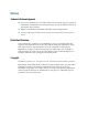
Chapter 2 Installing the Residential Gateway Mounting the Residential Gateway Vertically Some installations may require that you place the residential gateway in a vertical position. Use proper care when installing the residential gateway in a vertical position.
Mounting the Residential Gateway to the Wall Mounting the Residential Gateway to the Wall The following illustration shows the location and dimensions of the wall-mounting slots on the bottom of the residential gateway. Use the information on this page as a guide for mounting your residential gateway to the wall.
Chapter 2 Installing the Residential Gateway Connecting Your Computer to the Residential Gateway You can connect a computer to the residential gateway using one of the following methods: Ethernet Connection Wireless Connection Note: These instructions describe a PC connection. You could also connect another type of device with a wireless interface. See the owner's manual that came with the device for instructions.
Connecting Your Computer to the Residential Gateway Connecting the Computer with a Wireless Connection A wireless connection requires a wireless-enabled notebook or a computer with an 802.11b/g wireless network adapter installed. Complete these steps to connect the computer with a wireless connection. 4020210 Rev A 1 Connect the power adapter that came with the residential gateway to the POWER port on the residential gateway and to an electrical outlet. 2 Power on the residential gateway.
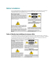
Chapter 2 Installing the Residential Gateway Connecting the DSL Interface Now that you have connected the gateway to power and you have made the LAN connections, you can connect the DSL interface (connection to the wall jack) as shown in the following illustration. This illustration shows all of the attached devices connected to the residential gateway.
Connecting an IP Set-Top to the Gateway Connecting an IP Set-Top to the Gateway For IPTV service, you must connect the residential gateway to an IP set-top. You can connect to an IP set-top using an Ethernet or coaxial connection. Ethernet Connection Complete the following steps to connect the residential gateway to an IP set-top through Ethernet for IPTV service. 4020210 Rev A 1 Ensure that the residential gateway is powered on.
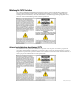
Chapter 2 Installing the Residential Gateway Coaxial Connection Complete the following steps to connect the residential gateway to an IP set-top with coaxial cable for IPTV service. 16 1 Ensure that the residential gateway is powered on. 2 Connect a coaxial cable from the HPNA port on the gateway to the TO WALL (Video In) port on the set-top. 3 Power on the IP set-top.
3 Chapter 3 Configuration and Operation The DDR2200 residential gateway contains web pages that show the current status of the residential gateway and that allow you to configure the device. Advanced users can configure parameters such as DHCP (Dynamic Host Configuration Protocol), wireless network settings, port forwarding, parental control, and so forth. This section provides information that you can use to configure and interact with the residential gateway through the user interface.