54Mb Hotspot-in-a-Box P-560 User’s Guide Revision 1.2 March 3, 2004 Copyright © 2002-2004 Gemtek Systems Holding BV www.gemtek-systems.
Federal Communication Commission Interference Statement This equipment has been tested and found to comply with the limits for a Class B digital device, pursuant to Part 15 of the FCC Rules. These limits are designed to provide reasonable protection against harmful interference in a residential installation. This equipment generates, uses and can radiate radio frequency energy and, if not installed and used in accordance with the instructions, may cause harmful interference to radio communications.
Copyright © 2002-2004 Gemtek Systems Holding BV. This user’s guide and the software described in it are copyrighted with all rights reserved. No part of this publication may be reproduced, transmitted, transcribed, stored in a retrieval system, or translated into any language in any form by any means without the written permission of Gemtek Systems Holding BV. Notice Gemtek Systems reserves the right to change specifications without prior notice.
User’s Guide Contents Contents Copyright ............................................................................................................................................. 3 Notice .................................................................................................................................................. 3 Trademarks ......................................................................................................................................... 3 CONTENTS .........
User’s Guide Contents Network ............................................................................................................................................. 41 Wireless............................................................................................................................................. 43 User ................................................................................................................................................... 44 Status ...................
User’s Guide Contents System | Configuration | NTP ........................................................................................................92 System | Configuration | Certificate ...............................................................................................93 System | Configuration | Save and Restore...................................................................................94 System | Configuration | Pronto...........................................................
User’s Guide About this Guide About this Guide Purpose This document provides information and procedures on hardware installation, setup, configuration, and management of the Gemtek Systems high performance 56Mb Hotspot-in-a-Box model P-560. The P-560 is a highly integrated Access Controller for public access areas. We will call it AC later in the manual.
User’s Guide Chapter 1 – Introduction Chapter 1 – Introduction Thank you for choosing the Gemtek Systems 54 Mb High Performance Hotspot-in-a-Box. The Gemtek Systems P-560 is a high performance and highly integrated Access Controller for public access networks. It combines a high-speed wireless LAN Access Point, an IP Router, a 4-port LAN Switch and a complete Access Controller for Wi-Fi Hotspots in one box.
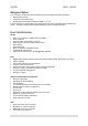
User’s Guide Chapter 1 – Introduction Management Options You can use the Access Controller management systems through the following interfaces: Web-browser interface Command Line interface (CLI) Simple Network Management Protocol (SNMP v1, v2, v3) The AC management system pages are organized the same way for the web-browser interface and the CLI. This user manual provides detailed description of each management option. Access Controller Features WLAN 802.
User’s Guide Chapter 1 – Introduction LAN switch Managed 4-port switch 10/100Mb, auto-sensing 802.1q/p tagged VLAN support (in preparation) Management Secure management via https, SSH, SNMP SNMP proxy SNMPv3 (incl.
User’s Guide Installation Installation This chapter provides installation instructions for the hardware and software components of the Access Controller P-560.
User’s Guide Installation Hardware Introduction General Overview Figure 1 – P-560 Access Controller General View The front panel of the Access Controller contains: A series of indicator lights (LEDs) that help describe the state of various networking and connection operations.
User’s Guide Installation Back Panel 1 2 Figure 2 – Back Panel of the P-560 The back panel of the Access Controller contains: Model and device name (see item 1 in figure above). The official device name is 54Mb Hotspotin-a-Box, model P-560. MAC address of the device. The label (item 2 in figure above) shows the WLAN interface MAC address of the device.
User’s Guide Installation The various states of the LEDs indicate different networking and connection operations as follows: Item LED Color Status Indication 1 Green On P-560 is active/working Blink P-560 is booting Orange On Writing to FLASH memory Green On PPPoE/PPTP/GRE tunnel for DSL is active on P-560 Off No active PPPoE/PPTP/GRE tunnel for DSL on P-560 2 Power Online 3 WAN Orange On WAN active/working 4 WLAN Orange On WLAN active/working 5 LAN (1, 2, 3, 4) Green On
User’s Guide Installation Connecting the Access Controller Use the following procedure to prepare your network connection to the Access Controller. Use the enclosed power adapter and power cord for power supply of your Access Controller. Step 1 Place the Access Controller on a flat work surface. Step 2 Connect one Ethernet patch cable to the LAN port of the Access Controller and to a free hub port on your local network.
User’s Guide Installation Initialization There are two choices for the first web browser connection to your Access Controller: either you enter your access controller's IP address and subnet (default networks settings) into the browser or you launch the KickStart utility that is provided with your product CD. The default network settings for your new access controller are: LAN port: IP 192.168.3.1 subnet 255.255.255.0 WAN port: IP 192.168.2.66 subnet 255.255.255.0 WLAN port: IP 192.168.4.
User’s Guide Installation The default administrator log on settings for all access point interfaces are: User Name: admin Password: admin01 Step 3 After successful administrator log on you will see the main page of the access controller’s Web interface: If second method is prefered follow the instuctions: Step 1 Gemtek Systems Install the KickStart utility from the Installation CD. Click Start > Programs > GSI > KickStart to launch the application.
User’s Guide Installation Step 2 Select your controller and right click. Select Open WEB item to launch the web management interface through the secure https connection: Step 3 Enter the Access Controller administrator login settings to access the web management interface. The default administrator log on settings for all controller interfaces are: User name: admin Password: admin01 Step 4 After successful administrator log on you will see the controller web interface.
User’s Guide Installation Step by Step Setup Step 1. Interface Set-Up In the network interface | configuration menu you can set the TCP/IP settings. Eth0 is preconfigured as the WLAN port of your Access Controller, Ixp1 is the WAN port, and Ixp0 is the LAN port. You can modify these settings according to your local network requirements. Make sure that IP subnets do not overlap.
User’s Guide Installation Figure 7 – RADIUS Settings On the second page: network interface | RADIUS servers you can specify up to 32 different RADIUS servers for authentication and accounting (see Figure 8 – RADIUS Servers). The first line of this table is the default server (can be configured as default). Thus, if a user cannot be associated to any specific service provider by his login name, the Access Controller will send authentication and accounting messages to the first RADIUS server on the list.
User’s Guide Installation The default user login page looks like the picture below: Figure 9 – Example of a Simple Login Page You have full flexibility to modify and adapt all these pages to your needs and personal designs. For initial set up and testing we recommend you use the default configuration, which will present a simple login window with input fields for user name and password. Enter any start page you like in the user interface | start page menu.
User’s Guide Chapter 3 – Universal Address Translation Chapter 3 – Universal Address Translation Universal Address Translation (UAT) allows Hotspot operators to offer true Plug&Play access for their subscribers. With UAT enabled, the Access Controller will automatically and transparently translate fixed IP settings (IP address, gateway, DNS, proxy server) on a user’s PC enabling him to connect to the broadband Internet service.
User’s Guide Chapter 3 – Universal Address Translation IP: 10.1.1.1/16 IP: 192.168.2.66/24 Conflict: Two subscribers connected to one Access Controller cannot use the same IP address. For instance, this situation can happen when DHCP and UAT are used in parallel. IP: 10.11.11.11 IP: 10.11.11.11 Work-around: Enable the DHCP service. IP Conflict IP: 10.11.11.11 Subnet: 255.255.0.0 Gateway: 10.11.1.
User’s Guide Chapter 4 – User Pages Chapter 4 – User Pages This chapter describes what the user pages are and how to manage them. Detailed instructions on how to change and upload new user pages are given below. When launching his/her web browser the user's initial HTTP request will be redirected to an operator defined set of web pages, further called the "user pages". User pages are: Welcome page– the first page presented to the user.
User’s Guide Chapter 4 – User Pages User Pages Overview Welcome Page Welcome page is the first page a Hotspot subscriber receives when he starts his web browser and enters any URL. By default it’s a very simple page and provides only a link to the login page. Figure 10 – Welcome Page The Hotspot operator can change the welcome page according its needs. See more details in section: Changing User Pages. Login Page The subscriber gets to the login page after clicking the link on the welcome page.
User’s Guide Chapter 4 – User Pages Logout Page Make sure the JavaScript is enabled on your Web browser; otherwise you will not receive the logout page. The Logout page contains the detailed subscriber’s session information and provides function for logging out of the network: Figure 12 – Logout Page Detailed AC subscriber’s session information includes: User – subscriber’s login name. User IP – subscriber’s logical network name (IP address). MAC Address – subscriber’s physical network address.
User’s Guide Chapter 4 – User Pages Help Page Click on the get help link in the login page for help tips related to network registration. A page appears similar to the following: Figure 13 – Help Page The Hotspot operator can change the help page according to its needs. See more details in section: Changing User Pages.
User’s Guide Chapter 4 – User Pages Changing User Pages As the Hotspot operator you can modify the user pages freely according to your personal needs and preferences. User Page templates can be either stored locally on the AC or on an external web server. See the Appendix: G) User Pages Templates Syntax to find the syntax and comments of all user pages. Use the user interface | configuration menu to modify user pages.
User’s Guide Step 4 Chapter 4 – User Pages Specify the new user page location in the location field (http://servername/filelocation): Do not try to upload other than supported formats. Such uploaded pages will not be displayed properly. Step 5 Save entered changes with the apply changes button: Step 6 Check for new uploaded user page (e.g. login): If at anytime you wish to restore factory default user pages, click the reset button under the system | reset menu.
User’s Guide Chapter 4 – User Pages Example for Internal Pages We will use the user pages templates from the Installation CD to show the example how to upload the internal pages. Follow the steps below: Step 1 Ensure that internal option is selected for all user pages you want to change.
User’s Guide Step 4 Chapter 4 – User Pages Click the upload button to upload specified templates and files. You do not need to upload all additional files at once. You can repeat the upload process a number of times until all necessary images are uploaded. Step 5 Check for the newly uploaded user pages and images to ensure that everything is uploaded and displayed correctly.
User’s Guide Chapter 4 – User Pages If at anytime you wish to restore the factory default user pages, click the reset button under the system | reset menu.
User’s Guide Chapter 4 – User Pages Extended UAM The Extensions feature (user interface | configuration menu) allows an external Web Application Server (WAS) to intercept/take part in the user authentication process externally log on and log off the user as necessary. It provides means to query user session information as well. See the following schemes to understand how the remote client authentication works. Scheme 1: Client AC WAS RADIUS Server 1. Initial Request 2. Fetch XSL 3. Renders HTML 4.
User’s Guide Chapter 4 – User Pages When the Web Application server has all needed data from the client, it must try to authenticate (6) the client. Authentication is done by the RADIUS server but through the AC. At this step the shared secret is used to make the connection between the WAS and the AC. The AC re-sends the authentication request to the RADIUS server (7). Depending on the status, appropriate authentication status must be returned back to the WAS but through the AC (8).
User’s Guide Chapter 4 – User Pages Parameters Sent to WAS Parameters that are sent to the WAS for user authentication pages redirection: parameter description nasid NAS server ID value. Can be changed or specified under the network interface | RADIUS | RADIUS settings menu nasip P-560 WAN IP address. Can be changed or specified under the network interface | configuration | interface configuration menu. cientip Client IP address. Cannot be defined manually. mac Client MAC address.
User’s Guide Chapter 4 – User Pages Network failed 113 Network connection failed. Accounting error 114 Accounting error. Too many users 115 Too many users connected. Unknown authorization error 120 Unknown authorization error. is RADIUS Reply-Message attribute value. If RADIUS responds with ReplyMessage(s), they are added to logon response. If RADIUS does not responds with Reply-Message, attribute is not added to output XML.
User’s Guide Chapter 4 – User Pages Failed to logoff 131 Failed to logoff user. Cannot resolve IP 132 Cannot resolve user IP. Unknown logoff error 140 Unknown logoff error. 3. Remote user status Script name: ppstatus.user Parameters: secret shared secret, to protect page from accidental use ip IP address of user to get status. username Username of the user to get status. All parameters are required. Script call example: https://P560/ppstatus.
User’s Guide Chapter 4 – User Pages 3E64C7967A36 00:01:10 0 bytes 0 bytes testlab unlimited unlimited unlimited 32 Mbps 32 Mbps 04:59:55 EAP Status detailed information by ID: id description 1 User name 2 User IP address
User’s Guide Chapter 5 – Command Line Interface Chapter 5 – Command Line Interface Introduction The CLI (Command Line Interface) software is a configuration shell for the Access Controller.
User’s Guide Chapter 5 – Command Line Interface SSH Connection Make sure that default access status is enabled on the AC before attempting to connect via SSH. Otherwise no SSH connection will be available. Connect the Access Controller via LAN or WAN ports using the enclosed UTP cable and start a SSH session (using an application as PuTTY). For example connect your device via the WAN port and then make a SSH connection to host IP: 192.168.2.66 (default WAN interface IP).
User’s Guide Chapter 5 – Command Line Interface connection ? Figure 20 – Connection Commands Network Network is a category of commands that configures controller interface settings, DNS, DHCP, UAT and RADIUS settings. A full list of all available network commands/subcommands and its parameters is available in the Appendix section D) CLI Commands and Parameters. The network commands themselves contain several subcommands and the subcommands again contain several parameters.
User’s Guide Chapter 5 – Command Line Interface Figure 23 – Configure Network (2) To get a list for available parameters on selected subcommand, type: network ?, (e.g.
User’s Guide Chapter 5 – Command Line Interface Wireless Wireless is a category of commands that configures controller basic and advanced wireless interface settings, access control list (ACL) and WDS. A full list of all available wireless commands/subcommands and its parameters is available in the Appendix section: D) CLI Commands and Parameters. The wireless commands themselves contain several subcommands and the subcommands again contain several parameters.
User’s Guide Chapter 5 – Command Line Interface User User is a category of commands that configures controller interface settings, affecting the user’s interface: redirection URL, free sites (walled garden), system management access, administrator login/password. A full list of all available user commands/subcommands and their parameters is available in the Appendix section: D) CLI Commands and Parameters.
User’s Guide Chapter 5 – Command Line Interface Status Status is a category of commands that’s displays: General devices status (model, firmware version, uptime, memory) All interface network settings (IP address/netmask, MAC address, gateway, RX/TX statistics) Currently running services (DHCP, routes, port forward, telnet, SNMP, UAT, ..). A full list of all available status commands/subcommands and their parameters is available in the Appendix section: D) CLI Commands and Parameters.
User’s Guide Chapter 5 – Command Line Interface Figure 34 – System Commands List Telnet To make a telnet connection, type the telnet command in the command line: telnet Figure 35 – Telnet Command The telnet client is activated and ready for a telnet session. Figure 36 – Telnet Session Quit the telnet to return to CLI interface. Reboot To stop the controller and reboot the device, type the reboot command in the command line. No configuration changes are done.
User’s Guide Chapter 6 – SNMP Management Chapter 6 – SNMP Management Introduction Another way to configure and monitor the Access Controller (P-560) via a TCP/IP network is SNMP (Simple Network Management Protocol). SNMP is an application layer protocol that facilitates the exchange of management information between network devices. It is part of the Transmission Control Protocol/Internet Protocol (TCP/IP) protocol suite.
User’s Guide Chapter 6 – SNMP Management and that its configuration is unaltered. authenticationFailure An authenticationFailure trap signifies that the SNMP entity, acting in an agent role, has received a protocol message that is not properly authenticated. linkDown A linkDown trap signifies that the SNMP entity, acting in an agent role, recognizes a failure in one of the communication links represented in the agent's configuration.
User’s Guide Chapter 6 – SNMP Management Use SNMP to Access MIB As shown in the picture Figure 37 – SNMP Network SNMP agent gathers data from the MIB. The agent can send traps (notification of certain events) to the SNMP manager, which receives and processes the traps. Traps are messages alerting the SNMP manager to a condition on the network such as improper user authentication, restarts, link status (up or down), MAC address tracking, and so forth.
User’s Guide Chapter 7 – Reference Manual Chapter 7 – Reference Manual This chapter contains Hotspot-in-a-Box web management reference information. The web management main menu consists of the following sub menus: Network Interface – device configuration settings affecting networking. User Interface – device configuration settings affecting the user interface. System – device system configuration settings directly applicable to the controller.
User’s Guide Chapter 7 – Reference Manual Pages – configure and upload user pages Upload – upload new internal user pages Headers – define http headers encoding and language Remote Authentication – allow external Web Application Server intercept/take part in user authentication process One Click – configure One Click roaming Administrator – administrator login and password change Start page – define start page URL Walled Garden – free web site list Web Proxy – web proxy settings for clients System Configu
User’s Guide Chapter 7 – Reference Manual Network Interface Network Interface | Configuration | Interface Configuration The interfaces eth0 and ixp0 on 2.21 firmware are bridged therefore they will be displayed as one eth0. The screen shots in this manual will not match with ones on your device. The Hotspot-in-a-Box contains up to three multi-purpose network interfaces: eth0, ixp0 and ixp1.
User’s Guide Chapter 7 – Reference Manual IP address of each interface should be from a different subnet; otherwise, you will receive an error message. Netmask – specify the subnet mask [[0-255].[0-255].[0-255].[0-255]].These numbers are a binary mask of the IP address, which defines IP address order and the number of IP addresses in the subnet. Gateway – interface gateway. For LAN type interfaces, the gateway can only be defined as WAN interface gateway.
User’s Guide Chapter 7 – Reference Manual Network Interface | Configuration | VLAN Up to 4094 VLANs can be created in the system. Virtual Local Area Networks (VLANs) are logical groupings of network resources. You can create your own VLANs on your AC using the network interface | configuration | VLAN menu.
User’s Guide Chapter 7 – Reference Manual Click the update and restart and apply changes to save your new VLAN. Check the interface | configuration | VLAN menu for new created VLAN: Figure 48 – Enable New VLAN Network Interface | Configuration | Route Under the network interface | configuration | route menu, static routes for the Ethernet interfaces can be set.
User’s Guide Chapter 7 – Reference Manual Network Interface | Configuration | Port Forwarding Port Forwarding is required when NAT is configured. NAT translates all internal addresses to one official IP address (WAN IP address). With port forwarding enabled it is possible to access internal services and workstations from the WAN interface. Port forwarding forwards TCP or UDP traffic trough the P560 controller’s local port to the specified remote port.
User’s Guide Chapter 7 – Reference Manual Network Interface | Configuration | Management Subnet Each network interface can have a management subnet. Use the network interface | configuration | management subnet menu to configure this feature on selected interface. When management subnet is enabled, port forwarding will NOT WORK when connecting from IP addresses that are in the management subnet's remote administrator's network.
User’s Guide Chapter 7 – Reference Manual With these settings applied, the administrator will be able to connect to devices behind the P560 on interface ixp0, if these devices use address in the range: 10.0.0.2 ... 10.0.0.254. The administrator is connecting via the Internet (from ixp1 interface). The administrator’s computer can have an address from 10.10.0.1 to 10.10.0.254. The P560 interface eth0 has two IP addresses – 192.168.3.1 and 10.0.0.1. Please note that devices which are using 10.0.0.2. – 10.0.
User’s Guide Chapter 7 – Reference Manual Figure 58 – DNS Redirection Settings The DNS server or DNS address can be obtained dynamically if DHCP, PPPoE and/or PPTP (for DSL) service is enabled. To add DNS server manually click the edit button in the action column and type in the DNS server’s IP address: Figure 59 – Edit DNS Redirection Settings IP address – enter the primary or secondary DNS server’s IP address [in digits and dots notation]. Save – click to save the new DNS server’s settings.
User’s Guide Chapter 7 – Reference Manual To edit the DHCP service configuration [DHCP server/DHCP relay], click the edit button in the action column: Figure 62 – Edit DHCP Configuration Settings Status – select status from drop-down menu: Disabled – disable the DHCP service on the selected interface DHCP Server – enabled by default DHCP Relay – to route DHCP through the external server, enable relay service Case 1 Configure the DHCP server Select the interface on which you want to configure the DHCP
User’s Guide Chapter 7 – Reference Manual Figure 64 – Edit DHCP Relay Settings Circuit ID – the unique DHCP relay parameter [optional, by default the MAC address of the device WAN interface is used]. If DHCP relay service is selected, the default WAN gateway is used automatically. Update – to update entered values, the following screen appears: Figure 65 – Apply or Discard DHCP Server Settings Apply Changes – to save entered new DHCP settings. Discard Changes – to restore previous values.
User’s Guide Chapter 7 – Reference Manual Network Interface | RADIUS RADIUS is an authentication and accounting system used by many Internet Service Providers (ISP). RADIUS enables ISPs to maintain a very large database of users. By using RADIUS, service providers can implement policy-based management of their subscribers’ base. RADIUS also helps ISPs to collect statistical data about their subscribers (e.g. amount of time, amount of transferred bytes, and session time).
User’s Guide Chapter 7 – Reference Manual Network Interface | RADIUS | RADIUS Settings General RADIUS settings are configured using the RADIUS settings menu under the network interface: Figure 66 – RADIUS Settings Configuration RADIUS Retries – retry count of sending RADIUS packets before giving up. RADIUS Timeout – maximum amount of time before retrying RADIUS packets [sec]. NAS Server ID – name of the RADIUS client.
User’s Guide Chapter 7 – Reference Manual Each setting in this table can be edited. Select RADIUS setting you need to update, click the edit next to the selected setting and change the value: Figure 67 – Edit RADIUS Settings Use the update button to update to an entered value.
User’s Guide Chapter 7 – Reference Manual Network Interface | RADIUS | RADIUS Servers Up to 32 different RADIUS servers can be configured under the RADIUS servers menu. By default, one RADIUS server is specified for the system: Figure 69 – RADIUS Servers Settings New – add new RADIUS server. Details – click on details to get more information about RADIUS server settings. Edit – edit selected RADIUS server settings. Delete – remove selected RADIUS server.
User’s Guide Chapter 7 – Reference Manual Figure 71 – Add New RADIUS Server Name – specify the new RADIUS server name. Default – check the check box to make the selected RADIUS the default server. Authentication IP – authentication RADIUS server IP address [dots and digits]. Authentication Port – specify the network port used to communicate with RADIUS [1-65535]. The port default value of 1812 is based on RFC 2138 "Remote Authentication Dialin User Service (RADIUS)".
User’s Guide Chapter 7 – Reference Manual Update – add new specified RADIUS server. Cancel – restore all previous values. After adding a new RADIUS server or editing an existing one, the following controls appears: Apply Changes – save changed configuration. Discard Changes – discard all changes. Restart – after applying changes to the system, you should restart the controller to make applied changes work.
User’s Guide Chapter 7 – Reference Manual Figure 74 – RADIUS Proxy Settings RADIUS Proxy Status – select [enabled] to enable the RADIUS proxy feature [enabled/disabled]. Authentication Port – specify the port on AC for listening the RADIUS authentication packets. The AC RADIUS proxy authentication port will accept only RADIUS authentication packets [1-65535, default: 1812]. Accounting Port – specify the port on AC for listening the RADIUS accounting packets.
User’s Guide Chapter 7 – Reference Manual Network Interface | RADIUS | Accounting Backup The administrator can backup the hotspot subscribers’ RADIUS accounting information in two ways: Via syslog protocol to the specified host Download to the selected location (e.g.
User’s Guide Chapter 7 – Reference Manual Network Interface | Tunnels This chapter describes the configuration of VPN tunnels. VPN tunnels can be used to secure management and AAA traffic between the hotspot network and the network operation center of the operator. The Gemtek Systems Access Controllers support PPTP and GRE tunnels. Furthermore PPP (Pointto-Point Protocol) can be use to authenticate the AC to a authentication server and to assign IP settings to the WAN port of the AC.
User’s Guide Chapter 7 – Reference Manual Encryption – enables use of MPPE encryption. When PPPoE tunnel is used, then no server IP is required - broadcast address will be used. To specify GRE tunnel for your controller click the edit button and enter the following: Figure 79 – Specify GRE Tunnel Service – select service GRE. Remote IP – IP address of GRE tunnel endpoint [IP address]. Interface IP – enter the IP address of GRE interface [IP address].
User’s Guide Chapter 7 – Reference Manual Network Interface | Tunnels | GRE Client for VPN GRE (Generic Routing Encapsulation) tunnel is one of the solutions for tunneling private network over the TCP/IP connection (e.g. PPTP, L2TP, PPPoE). GRE tunnel does not use encryption. It only encapsulates data and sends it over the Internet. So the administrator should take care that no unencrypted private information is going through the GRE tunnel.
User’s Guide Chapter 7 – Reference Manual Network A (administrator's computer with Network Management System); we shall call this network (192.168.82.0/24) “Net A”. Network: Netmask: Router: 192.168.82.0 255.255.255.0 192.168.82.16 GRE server has two interfaces, LAN and WAN: LAN IP: WAN IP: 192.168.82.16 211.139.210.123 Settings in GRE tunnel page: GRE Remote Host: 211.139.210.123 GRE Route: 192.168.82.0/24 Network B has subscribers on wireless P-560 interface (eth0) we shall call this network (192.
User’s Guide Chapter 7 – Reference Manual GRE Interface Netmask – enter the netmask of GRE interface [dots and digits]. GRE interface IP/Netmask settings is important when configuring the GRE server. GRE Route – this is the destination network for the GRE tunnel in the combined node/subnet format [IP address/N]. The /N stands for the number of bits that are in the network address. There are 32 bits, so we have 32-N bits left that are part of our network. The first N bits of x.x.x.x correspond to x.0.0.
User’s Guide Chapter 7 – Reference Manual Network Interface | Wireless The Hotspot-in-a-Box has the wireless interface (eth0) and can act as the Access Point. Using the network interface | wireless menu, the system administrator can create a wireless network infrastructure (WDS), set the wireless basic settings (SSID, network mode: 802.11b/802.
User’s Guide Chapter 7 – Reference Manual associated, the Access Point sets the Short Preamble capability bit to 0 and Long Preamble is used. In all other cases, the Short Preamble capability bit is set to 1 and Short Preamble is used. CWmin – indicates contention window size minimum. NonERP Protection – indicates Dynamic mode what means that NonERP protection bit is set to 0 or 1 whether NonERP BSSs or stations are associated to AP or not.
User’s Guide Chapter 7 – Reference Manual Network Interface | Wireless | Advanced Use the network interface | wireless | advanced menu to configure the layer 2 client isolation, SSID broadcasting or threshold values or wireless card output power: Figure 87 – Advanced Wireless Setting Layer 2 Isolation – Layer 2 wireless client separation. Connected clients with user isolation function enabled cannot access each other directly.
User’s Guide Chapter 7 – Reference Manual Figure 88 – WPA with Pre-shared Key Security Settings Pre-shared Key – specify the pre-shared key for WPA security [8-64 characters]. The encryption pre-shared key must also be entered into the WLAN card configuration of the mobile clients. Update – click the button to apply security setting to your wireless network. WPA with RADIUS server makes use of external AAA (RADIUS) server to generate and exchange dynamic WPA keys between P-560 and user station.
User’s Guide Chapter 7 – Reference Manual Figure 91 – ACL Service ACL service – click the edit button to enable or disable the access control service on device. By default the ACL service is disabled and all mobile clients connections to the AC are allowed (no ACL rules are applied to the mobile clients). Default ACL policy – click the edit button to change the default ACL policy [allow/deny].
User’s Guide Chapter 7 – Reference Manual Network Interface | Wireless | WDS A WDS (Wireless Distribution System) allows you to create a wireless network infrastructure. Normally, the access points must be connected with a wire (LAN), which is generally an Ethernet connection in business applications. Once connected, these access points create wireless cells allowing a wireless connection.
User’s Guide Chapter 7 – Reference Manual Figure 94 – Add WDS Link MAC for Per AP [1-8] – enter wireless interface (eth0) MAC address of the peer AP for the WDS link [6-HEX pairs separated by colon [1-9] [A-F] [a-f]]. You can discover the wireless interface (eth0) MAC address of your P-560 in the system | status page. Update – click the button to update you system with WDS links.
User’s Guide Chapter 7 – Reference Manual User Interface Use the user interface menu to configure device settings affecting the user interface. If you need to configure the: welcome/login/logout/help/unauthorized pages, administrator settings, start page or free sites, use the user interface menu. Figure 95 – User Interface Menu User Interface | Configuration | Pages Detailed description about user page customization is given in the Chapter 4 – User Pages.
User’s Guide Chapter 7 – Reference Manual Welcome page with redirect option selected redirects the user authentication process to the specified location. The user welcome/login/logout page can be implemented as simple HTML (not required to use the .XSL or default user pages templates) in such case. The redirect location URL should be specified as Walled Garden URL, otherwise the redirect would NOT WORK.
User’s Guide Chapter 7 – Reference Manual P560 device supports some http META tags. Syntax of such META tags: Currently P560 supports Content-Type and Content-Language tags: Content-Type is used to define document char set (used, when text has non-Latin letters, like language letters). Content-Language may be used to declare the natural language of the document. P560 automatically adds defined content-type and content-language to generated XML. Then user pages (.
User’s Guide Chapter 7 – Reference Manual User Interface | Configuration | One-Click Roaming One-Click roaming is the ability of T-mobile customers to use the T-mobile Hotspot service in Third Part Hotspots, while the authentication and billing is entirely realized through T-mobile. The Third Part Hotspot only provides the access to the T-mobile WLAN platform. Use the network interface | configuration | one click menu to configure this feature. By default One-Click roaming is disabled.
User’s Guide Chapter 7 – Reference Manual Client AC T-Mobile Portal RADIUS Server Welcome page is loaded Select T-Mobile Open popup Login user Enable source routing Open window / redirect to T-Mobile portal Logout user Cancel source routing Authentication Logout user Redirect routing to Welcome page Welcome page Figure 106 – One-Click Roaming diagram When T-mobile user attempt connect to internet it is redirected to ‘Welcome Page’ on access controller.
User’s Guide Chapter 7 – Reference Manual To edit or change the administrator settings simply click the edit button: Figure 108 – Change Administrator Settings Username – administrator username for access to Access Controller (e.g. web interface, CLI mode) [1-32 symbols, spaces not allowed]. Idle Timeout – amount of administrator inactivity time, before automatically disconnecting administrator from the web interface [300-3600 seconds]. The default idle time: 10minutes (600 seconds).
User’s Guide Chapter 7 – Reference Manual Figure 111 – Walled Garden Edit – edit the selected URL or host. All settings become available for editing. Delete – delete the selected URL or host. New URL – click the new URL button and enter the new URL and its description. Save entered information by clicking the update button: Figure 112 – Add New URL part 1 URL for User – define full URL address [www.gemtek-systems.com].
User’s Guide Chapter 7 – Reference Manual User Interface | Web Proxy The enabled web proxy allows any clients’ connections with configured proxy settings on their browsers. The AC accepts any client proxy configurations and grants the access to the Internet. The system administrator should list only ports the AC is listening on for proxy requests. Figure 115 – Web Proxy Web proxy is enabled by default and the port numbers are: 3128 and 8080.
User’s Guide Chapter 7 – Reference Manual System Use the system menu to configure such system utilities: Syslog – for sending system and debug messages via the syslog protocol. Trace system – trace such controller services as PPTP and PPPoE. Clock – manual setting of internal device clock. NTP – set the Network Time Protocol service on the AC. Certificates – upload your own SSL certificate and private key files for server. Save and Restore – save current AC configuration and restore.
User’s Guide Chapter 7 – Reference Manual Save – save changes. The syslog messages will be started to send to the specified host. Cancel – restore the previous values. System | Configuration | Trace System The trace system utility debugs system services and protocols if malfunction occur. Trace system works with started services as DHCP, PPTP, PPPoE, telnet and SNMP and shows number of system messages according to the selected history size.
User’s Guide Chapter 7 – Reference Manual To adjust the clock settings, click the change button: Figure 122 – Set Clock Settings Date – specify new date value [year/month/day]. Time – specify time [hours: minutes]. Time Zone – select the time zone [-12.00 – 14.00]. If the NTP service is enabled the selected time zone will be applied to the clock settings also. If the NTP server (see the next section for reference) is enabled on the system, no manual clock setting is available except time zone.
User’s Guide Chapter 7 – Reference Manual Figure 126 – Add New NTP Host Host – add additional NTP service hosts [1-128]. This NTP server will be used, if connection to the first defined NTP server is lost. System | Configuration | Certificate You can upload your own SSL certificates files for HTTP connection using the certificate menu under the system | configuration menu: Figure 127 – Certificate Upload Only these certificate files are accepted: Server PEM-encoded X.
User’s Guide Chapter 7 – Reference Manual Figure 129 – Default Certificate Properties Flash – upload new certificates into the controller. Cancel – cancel new certificate upload. System | Configuration | Save and Restore You can save your current device configuration file locally using the save and restore menu under the system | configuration menu: Figure 130 – Save and Restore Such device configuration is saved in the specific format file (.
User’s Guide Chapter 7 – Reference Manual Figure 132 – Upload Configuration File Flash – click the button to apply configuration setting to the device. System | Configuration | Pronto The goal of the pronto-compatible agent program is to ensure that a partner’s hotspot is interoperable with Pronto’s Hotspot OSS. Pronto compatibility agent is used to download and overwrite current configuration (only some parameters which are listed below) from pronto server using WEB proxy.
User’s Guide Chapter 7 – Reference Manual Edit – click to edit required parameter. Change Pronto status to enable and configure the rest Pronto settings. To configure Pronto settings, click the edit button next to appropriate parameter and specify value. Reboot the device. Figure 134 – Configure Pronto Settings Update – click the button to apply pronto agent settings. Cancel – restore the previous value. After reboot device’s configuration will be changed automatically.
User’s Guide Chapter 7 – Reference Manual Service – select services that access you need to control [all/ssh/telnet/snmp]. Telnet service should be also enabled in the system | access | telnet to allow the telnet access to the controller. Otherwise, the client or network will not get telnet access. Network Address – specify the network or host address with netmask in bit format separated by dash. The /N stands for the number of bits that are in the network address.
User’s Guide Chapter 7 – Reference Manual Figure 138 – Change Telnet Status Enabled – connection via telnet to AC is enabled. Disabled – connection via telnet to AC is disabled. Save – click the button to save the configuration. Cancel – restore the previous value. System | Access | AAA It is recommended to use the Gemtek Systems product Smart Client Manager (S-200) for EAP authentication methods.
User’s Guide Chapter 7 – Reference Manual Current RADIUS secret value is only displayed and CANNOT be changed under the AAA menu. To change the RADIUS secret value use the network interface | RADIUS | servers menu. System | Access | UAT With Universal Address Translation (UAT) enabled, the Hotspot-in-a-Box will automatically and transparently translate fixed IP settings (IP address, gateway, DNS, proxy server) on a user’s PC so that he can connect to the broadband Internet service.
User’s Guide Chapter 7 – Reference Manual IP address and netmask should be combined and used as pool for users on this interface. Note that count of available IP addresses will become maximum user count on this interface - if there will be no free IP addresses, access will be rejected because of lack of IP addresses. System | Access | Isolation Isolation mechanism under the system | access | isolation menu increases the security of the AC users.