DRAFT 4038769 Rev 01 Cisco Model VEN401 and VEN402 User Guide Draft
DRAFT
DRAFT Please Read Important Please read this entire guide. If this guide provides installation or operation instructions, give particular attention to all safety statements included in this guide.
DRAFT Notices Trademark Acknowledgments Cisco and the Cisco Logo are trademarks of Cisco Systems, Inc. and/or its affiliates in the U.S. and other countries. A listing of Cisco's trademarks can be found at www.cisco.com/go/trademarks. Third party trademarks mentioned are the property of their respective owners. The use of the word partner does not imply a partnership relationship between Cisco and any other company. (1005R) The Wi-Fi Protected Setup mark is a mark of the Wi-Fi Alliance.
DRAFT Contents IMPORTANT SAFETY INSTRUCTIONS v Power Source Warning ............................................................................................. vi Ground the Product ................................................................................................... vi Protect the Product from Lightning ........................................................................ vi Verify the Power Source from the On/Off Power Light ......................................
DRAFT Contents Installing the Devices 1 Front Panel ................................................................................................................................ 2 Back Panel ................................................................................................................................. 3 Connecting the VEN401 Access Point to a Residential Gateway or Router .................... 4 Connecting the VEN402 Client to a Set-Top, DVR, or DMA ...................................
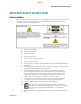
DRAFT IMPORTANT SAFETY INSTRUCTIONS IMPORTANT SAFETY INSTRUCTIONS Notice to Installers The servicing instructions in this notice are for use by qualified service personnel only. To reduce the risk of electric shock, do not perform any servicing other than that contained in the operating instructions, unless you are qualified to do so. 4038769 Rev 01 1) Read these instructions. 2) Keep these instructions. 3) Heed all warnings. 4) Follow all instructions. 5) Do not use this apparatus near water.
DRAFT IMPORTANT SAFETY INSTRUCTIONS 14) Refer all servicing to qualified service personnel. Servicing is required when the apparatus has been damaged in any way, such as a power-supply cord or plug is damaged, liquid has been spilled or objects have fallen into the apparatus, the apparatus has been exposed to rain or moisture, does not operate normally, or has been dropped. Power Source Warning A label on this product indicates the correct power source for this product.
DRAFT IMPORTANT SAFETY INSTRUCTIONS Provide Ventilation and Select a Location Remove all packaging material before applying power to the product. Do not place entertainment devices (such as VCRs or DVDs), lamps, books, vases with liquids, or other objects on top of this product. Do not block ventilation openings. Do not place this apparatus on a bed, sofa, rug, or similar surface. Do not place this apparatus on an unstable surface.
DRAFT
DRAFT Compliance Information Compliance Information United States FCC Compliance This device has been tested and found to comply with the limits for a Class B digital device, pursuant to part 15 of the FCC Rules. These limits are designed to provide reasonable protection against such interference in a residential installation. This equipment generates, uses, and can radiate radio frequency energy.
DRAFT Compliance Information Dynamic Frequency Selection (DFS) Dual Band Frequencies Some configurations of this product may operate in the 5150-5250 MHz and 5470-5725 MHz bands. If you select any channel in these frequency ranges, the product is restricted to indoor operation only per FCC guidance. The use of this product on the affected frequencies when outside is in non compliance of the FCC regulations and guidelines.
DRAFT CE Compliance CE Compliance Declaration of Conformity with Regard to the EU Directive 1999/5/EC (R&TTE Directive) This declaration is only valid for configurations (combinations of software, firmware and hardware) supported or provided by Cisco Systems for use within the EU. The use of software or firmware not supported or provided by Cisco Systems may result in the equipment no longer being compliant with the regulatory requirements.
DRAFT Europe Europe The CE mark and class-2 identifier are affixed to the product and its packaging. This product conforms to the following European directives: -1999/5/EC National Restrictions This product operates in the 5 GHz Wi-Fi bands and shall only be used indoors. Disclaimer Cisco Systems, Inc. assumes no responsibility for errors or omissions that may appear in this manual. We reserve the right to change this manual at any time without notice.
DRAFT Open Source GNU GPL Statement Open Source GNU GPL Statement Cisco VEN401 and VEN402 models contain, in part, certain free/open source software ("Free Software") under licenses which generally make the source code available for free copy, modification, and redistribution. Examples of such licenses include all the licenses sponsored by the Free Software Foundation (e.g.
DRAFT
DRAFT About This Guide About This Guide Introduction Congratulations on choosing the Cisco® VEN401 plus VEN402 Video Bridge Solution for the Connected Home experience. By connecting your video devices wirelessly, you are now free to place your televisions and video devices almost anywhere in the home. The small shape and unique design of the VEN401 plus VEN402 devices provide a stylish solution without pulling wires through walls or along floorboards.
DRAFT
DRAFT 1 Chapter 1 Installing the Devices Introduction This chapter provides information to install the VEN401 Access Point and VEN402 Client devices in home network. In This Chapter 4038769 Rev 01 Front Panel ............................................................................................... 2 Back Panel ................................................................................................ 3 Connecting the VEN401 Access Point to a Residential Gateway or Router............
DRAFT Chapter 1 Installing the Devices Front Panel The front panel of your devices have the following indicators and functions: Note: This illustration may vary from the actual product.
DRAFT Back Panel Back Panel The back panel of your devices have the following ports and functions: Note: This illustration may vary from the actual product.
DRAFT Chapter 1 Installing the Devices Connecting the VEN401 Access Point to a Residential Gateway or Router Complete the following steps to connect the VEN401 Access Point to a residential gateway or router. 4 1 Connect the 12 VDC Power Supply plug to the wall power outlet. Use only the power adapter provided with this product. 2 Connect the power jack to the power port on the VEN401. 3 Connect one end of the RJ-45 Ethernet cable to the Ethernet port on the VEN401.
DRAFT Connecting the VEN402 Client to a Set-Top, DVR, or DMA Connecting the VEN402 Client to a Set-Top, DVR, or DMA Complete the following steps to connect the VEN402 Client to a set-top, DVR, or DMA. 4038769 Rev 01 1 Connect the 12 VDC Power Supply plug to the wall power outlet. Use only the power adapter provided with this product. 2 Connect the power jack to the power port on the VEN402. 3 Connect one end of the RJ-45 Ethernet cable to the Ethernet port on the VEN402.
DRAFT Chapter 1 Installing the Devices Pair Devices Pairing a VEN402 Client Device Complete the following steps to pair the VEN401 access point with a VEN402 client device. Note: The VEN402 can only be paired with a VEN401. 1 Press the WPS button on the client device. The WPS LED flashes. Note: You have 2 minutes to perform step 2. 2 Click the WPS button on the VEN401 Access Point. The WPS LED flashes. When the devices are paired, the WPS LED remains lit for a short time.
DRAFT 2 Chapter 2 Web-Based User Interface Introduction To facilitate in-home customization and troubleshooting, the VEN401 plus VEN402 Video Bridge Solution includes a web-based user interface. The web-based user interface allows you to customize your Wi-Fi security and access other configurable features. The parameters accessed from the user interface are typically managed by your service provider.
DRAFT Chapter 2 Web-Based User Interface Login Complete the following steps to determine the IP address of your device and log in to the web-based user interface for your device. 8 1 The VEN 401/402 receive their IP addresses via DHCP from the connected router or gateway. Please, refer to your router or gateway documentation to determine the IP address. 2 Open a web browser on your computer. 3 Type the DHCP-provided IP address in the URL address field and then press Enter.
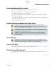
DRAFT Basic Setup Basic Setup Use the Setup screen to define the Internet Protocol (IP) configuration for your device. 1 2 Choose your Dynamic Host Configuration Protocol (DHCP) option per the following guidelines: Enabled: If your network includes a DHCP server for dynamic allocation of IP addresses, choose this option if you want DHCP to assign an IP address and subnet mask to the device.
DRAFT Chapter 2 Web-Based User Interface 3 10 – Primary DNS (Optional): Enter the IP address of the primary the Domain Name System (DNS) server that is used in your network. Use the same value that is used for the PCs on your local area network (LAN). Typically, your service provider provides this address. This address is required if you use a host name instead of an IP address in any configuration field in the configuration windows.
DRAFT Wireless Setup Wireless Setup Basic Wireless Settings Use the Basic Settings screen to the wireless interface for your device. 1 If you are configuring a VEN402 client device, you may enter the Network Name (SSID) for the wireless network you want to join in the field provided. Otherwise, go to step 2. 2 From the Wireless Network Wireless Interface field, select which wireless interface you want to configure.
DRAFT Chapter 2 Web-Based User Interface 12 4 Your device selects the optimum Control Channel for Wireless-N(5GHz) networking by default. If you want to configure the Control Channel manually, select another setting form the drop-down menu. 5 Use the following guidelines to configure the remaining fields: Note: This list below varies based on the code version on your device. If you have a question about any field, please contact your service provider.
DRAFT Wireless Setup 6 TPC Mitigation (db): Power Mitigation factor (in db). No-Acknowledgement: When enabled, wireless devices will not acknowledge each transmitted packet. This may cause more efficient throughput in low RF noise environments, but will degrade performance in noisy environments. The default is Off. APSD Support: Automatic Power Save Delivery (APSD) is a special powersaving mode to achieve end-to-end QoS. This option is available if you enabled WMM Support.
DRAFT Chapter 2 Web-Based User Interface 1 From the BSS-MAC(SSID) field, select the wireless BSSID interface you want to configure. 2 Do you want to enable this interface? a If yes, select Enabled for the BSS-Enabled field and continue with step 3. b If no, select Disabled and skip to the last step. 3 For added security, you should change the default SSID (Cisco) in the Network Name (SSID) field to a unique name. Note: The SSID is the network name shared among all points in a wireless network.
DRAFT Wireless Setup MAC Filter Settings Wireless access can be filtered by using the MAC addresses of the wireless devices transmitting within your network. 1 From the Select BSSID field, select the device you want to configure. 2 Do you want to use the Wireless MAC Filter feature for the device selected? a If yes, select Enabled and continue with step 3. b If no, select Disabled and skip to the last step.
DRAFT Chapter 2 Web-Based User Interface 5 Click the Save Settings button to apply your changes or Cancel Changes button to cancel. Security Settings Use this screen to configure the security of your wireless network. Complete the following steps to select a security mode for a specific BSSID. 1 2 16 Are you configuring a VEN401 or VEN402 device? If you are configuring a VEN401, select the wireless BSSID interface you wish to configure from the Select BSSID drop-down menu.
DRAFT Wireless Setup 3 4 WPA2-Personal—WPA2-Personal is a stronger encryption method than WPA-Personal. This method offers three encryption methods, TKIP, AES, and TKIP or AES, with dynamic encryption keys. Mixed WPA2 Personal/WPA Personal—This options supports both WPA and WPA2 clients. Did you select WEP? If yes, continue with the WEP Settings (on page 17) section to complete your security setup.
DRAFT Chapter 2 Web-Based User Interface If no, leave the Passphrase field empty and continue with step 3. 3 Enter the WEP key(s) manually in the fields provided (Key 1-4). 4 To indicate which WEP key to use, select the appropriate Transmit (TX) Key number from the drop-down menu. 5 Click the Save Settings button to apply your changes or Cancel Changes button to cancel.
DRAFT Wireless Setup Wi-Fi Protected Setup Set Up WPS on the VEN401 Use this screen to enable the Wi-Fi Protected Setup (WPS) feature on your VEN401 Access Point device. 1 From the Select BSSID drop-down menu select the wireless BSSID interface you want to configure. 2 From the WPS Configuration drop-down menu select Enabled to enable the WPS feature. 3 If your client device has a WPS button, complete the steps below to pair your devices. Otherwise, skip to step 4.
DRAFT Chapter 2 Web-Based User Interface 4 If your client device has a WPS PIN or passcode, complete the steps below: a Enter your PIN in the field provided. b Click the Register button. c After the client devices has been configured, click the OK button. 5 Click the Save Settings button to apply your changes or Cancel Changes button to cancel. 6 Refer back to your client device or its documentation for further instructions.
DRAFT Wireless Setup d Skip to the last step. 4 If your client device has a WPS PIN or passcode, complete the steps below: a Enter your PIN in the field provided. b Click the Register button. c 5 After the client devices has been configured, click the OK button. Click the Save Settings button to apply your changes or Cancel Changes button to cancel. Associated Devices Use this screen to list the devices associated with a specific SSID.
DRAFT Chapter 2 Web-Based User Interface Administration Setup Management Settings Use this screen setup or change your password, LAN Port, or IGMP setting. Password Complete the following steps to setup or change the password you are prompted to provide when you access the web-based utility. Note: The default password is admin. 1 Enter the current password in the Old Password field. 2 Enter the new password in the New Password field. 3 Re-enter the new password in the Confirm Password field.
DRAFT Administration Setup IGMP The Internet Group Membership Protocol (IGMP ) feature improves multicasting for LAN-side clients. Select Enabled if your clients support IGMP, otherwise, select Disabled. Click the Save Settings button to apply your changes or Cancel Changes button to cancel. Log Settings Use this screen to configure the device to record system activity in a log or to view the log report. Configure Log Settings Complete the following steps to enable or disable log reporting.
DRAFT Chapter 2 Web-Based User Interface 2 Select one of the following options from the Mode drop-down menu: Local—Select this option to retrieve logs from the local server. When this option is selected, the Server IP and Server UDP Port fields are not applicable. Remote—Select this option to send logs to a system server. When this option is selected, the Server IP and Server UDP Port fields are required. 3 Enter the Server IP Address of your syslog server.
DRAFT Administration Setup Diagnostics Use this screen to execute a ping test or trace route request. The ping test allows you to check the connections of your network devices, including connection to the Internet. Ping Test Complete the following steps to execute a ping test. 4038769 Rev 01 1 Enter the IP address or Fully Qualified Domain Name (FQDN) that you want to ping in the Target IP/FQDN field. This can be either a local (LAN) or Internet (WAN) IP address.
DRAFT Chapter 2 Web-Based User Interface Trace Route Parameters Complete the following steps to execute a trace route request. 1 Enter the desired IP address or Fully Qualified Domain Name (FQDN) in the Target IP/FQDN field. This can be either a local (LAN) or Internet (WAN) IP address. 2 Click the Start Trace Route button. The results are displayed. Backup Settings The Backup screen allows you to back up or restore the device’s settings using a configuration file.
DRAFT Administration Setup Factory Default Settings The Factory Defaults screen allows you to restore the device’s configuration to its factory default settings. (An alternative method is to press and hold the Reset button on the back panel of your device for approximately ten seconds.) Path: Administration > Factory Defaults Restore Default Settings—Click this button to restore settings to the factory default values. You will be prompted to confirm or cancel the restore request.
DRAFT Chapter 2 Web-Based User Interface Path: Administration > Upgrade Upgrade Firmware Follow the on-screen instructions to upgrade the firmware manually. Software File Name—Click the Browse button and select the firmware upgrade file. Update Software—After you have selected the appropriate file, click this button, and follow the on-screen instructions.
DRAFT Administration Setup Reboot The Reboot screen allows you to gracefully stop and restart the device. Performing a reboot allows you to save any configuration changes and to reboot the device to make the changes take effect. Path: Administration > Reboot Click Save/Reboot to reboot the device. The restart will terminate the Internet connection.
DRAFT Status Information Status Information General System Status Information Use this screen to view general information for your device. Device Information Hardware Version—Provides the version number of the device’s hardware. Software Version—Provides the version number of the device's software. Bootloader version—Provides the version number of the bootloader. Manufacturer—Provides the manufacturer name. Serial Number—Provides the serial number of the device.
DRAFT Status Information System Uptime—Provides the length of time the device has been active. System date and time—Provides the current date and time of the device. Ethernet Link IP Address—Provides the device's IP address, as it appears on your local network. MAC Address—Provides the device’s MAC address. Default Gateway—Provides the default gateway IP address. DHCP Lease Time—Provides the length of time for the DHCP lease setting.
DRAFT Status Information Network Name (SSID)—Provides the name of the wireless network. SSID Broadcast—Indicates if the SSID broadcast setting is enabled or disabled. Radio Status—Indicates if the radio is enable or disabled. Security—Provides the wireless security method. Radio Band—Provides the radio band setting. Current Channel-Provides the channel associated with the frequency that the radio band uses.
DRAFT 4038769 Rev 01 33
DRAFT Cisco Systems, Inc. 5030 Sugarloaf Parkway, Box 465447 Lawrenceville, GA 30042 678 277-1120 800 722-2009 www.cisco.com This document includes various trademarks of Cisco Systems, Inc. Please see the Notices section of this document for a list of the Cisco Systems, Inc. trademarks used in this document. Product and service availability are subject to change without notice. © 2011 Cisco and/or its affiliates. All rights reserved.