Gemtek Technology Co., Ltd. WL-818F Wireless 11g Cardbus Adapter User’s Guide Version 1.
Copyright statement No part of this publication may be reproduced, stored in a retrieval system, or transmitted in any form or by any means, whether electronic, mechanical, photocopying, recording, or otherwise without the prior writing of the publisher. July.
Contents 1. Introduction ............................................................................................................... 3 2. Wireless LAN Basics ................................................................................................ 4 3. Installation for Windows platform ........................................................................... 5 3.1. Installation Overview…………………………………………………………………………………..6 3.2. Install Procedure for Windows XP……………………………………………………….7 3.3.
1. Introduction Thank you for purchasing your Wireless LAN 802.11g Adapter. This Quick Installation Guide will assist you with the installation procedure. The package you have received should contain the following items: • Wireless LAN 802.
2. Wireless LAN Basics Wireless LAN (Local Area Networks) systems offer a great number of advantages over a traditional, wired system. Wireless LANs (WLANs) are more flexible, easier to setup and manage and often more cost effective than their wired equivalence. Using radio frequency (RF) technology, WLANs transmit and receive data over the air, minimizing the need for wired connections. Thus, WLANs combine data connectivity with user mobility, and, through simplified configuration, enable movable LANs.
3. Installation for Windows platform The following section will assist you in installing wireless LAN Adapter successfully. You will first install software (Utility) and then insert / attach the Wireless LAN Adapter to your system, and finally set the network properties to accommodate resource sharing and select the type of wireless network that you wish to install. The Wireless LAN card can easily be installed and used, without bothering to connect cables for keeping your computer to use network resources.
3.1. Installation Overview Here are some steps you will perform in establishing your wireless network connection: Install the Access Point at first. AP is needed in case of Infrastructure network mode. Install the software using the Install CD. Install the Wireless LAN Card (WIRELESS LAN 802.11g Adapter). Install the network protocol(s) required to communicate on your network. Most likely you will need the TCP/IP protocol.
3.2. Install Procedure for Windows XP Important Notice In order to make right use of WPA, please ensure that your current Wireless Adapter’s driver, and Wireless Utility can support it, WPA needs 802.1x authentication (when RADIUS mode is chosen), though the Operating System must also support 802.1x protocol. For Microsoft’s OS family, only Windows XP has incorporated this by default. The rest of the OS must installed 3er party’s client software such as Funk ODySSey.
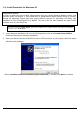
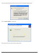
Once your system detected the driver, Microsoft will show a warning message as below. Click “ Continue Anyway ” for next step. After copy the file to your system, then the setup is finish.
3.3. Install Procedure for Windows 98/ME/2000 Note: Do not insert the WLAN Adapter until you are asked to do so, failure of which may result in unsuccessful installation of your WLAN device. Please follow the following steps one by one in order to install the WLAN Adapter successfully. 1. Power on your computer and allow Windows 98/ME/2000 to load fully. 2. Be sure that the Wireless LAN 802.11g Adapter is not inserted yet. 3.
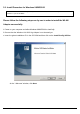
4. Accept the license agreement. Accept the license agreement. Click Yes to accept. Click Yes to finish the setup.
5. Insert / attach Wireless LAN 802.11g Adapter to your system Windows will recognize the WLAN adapter and auto detect the driver, if the system did not find the driver automatically, please install the driver manually. Click Yes to finish the installation.
6. Click the right button of mouse on My Computer Properties Hardware Device Manager. Check whether it has WLAN adapter in one of the sockets or not. If you find Wireless Network PC Card in one of the sockets, it means the card is detected properly. 7. Click right button of mouse on the Network Neighborhood.
8. Select Properties from the pop up menu. For Windows 98 the network’s properties box appears. * For Windows ME and 2000, please select the Local Area Connection’s properties to check the following menu. 9. Click on the General tab and then click on the Install button. Select Network Component Type box appears. Click on the Protocol then click the Add button.
10. Select Network Protocols box appears. From the list of network protocols list, select NetBEUI, then click OK. 11. The NetBEUI protocol is now installed. After clicking on OK return back to Network Component Type box. 12. Repeat the step 9 and 10 to add IPX/SPX protocol.
13. Click on the TCP/IP option for setting the IP address for your computer. You can select either Obtain an IP address automatically or Use the following IP address setting. If your choice is the second one then enter the IP value, Subnet masking, DNS, Domain/ Workgroup name, and Gateway Address values. After setting these parameters appropriately, click OK to return to Network Component Type and you can select the File and Printer Sharing options as well for sharing your computers resources. Click on OK.
Uninstall Procedure Step 1: If you want to uninstall the WLAN adapter, just simply click Start Menu Program Wireless Network Uninstall, it shall uninstall all related programs. Step 2: Restart your Computer.
4. Configuration Utility Wireless LAN 802.11g Wireless LAN adapter uses its own management software. All functions controlled by user are provided by this application. Usually this application starts automatically, or click icon from Start Menu to start the Utility application. A new icon should appear in your Icon tray. If the icon is in red, it means that Wireless LAN 802.11g NIC configuration is invalid or incomplete. Sometimes icon can be colored in yellow.
User can navigate through “sheets”, by clicking tabs. “X” button will minimize window. To provide more information, click “More…” button. Below description explains the use and meanings of the various screen messages.
4.1 Link Information - Connected To Network This field is used to display the current status of connection. When the state shows “Connected to Network“ means normal flow of operation in Infrastructure mode. The PC is connected to access point. Networking is available. A state of “Scanning” means that the node is searching for available access point and detecting the SSID for an available access point within range.
Shows the channel of the radio and transmit rate being currently used for an active connection. This value has no meaning when the radio is “Scanning” - Link Quality The Link Quality bar graph is only active when the node is in Infrastructure Mode. The bar graph displays the quality of the link between the node and Access Point. - Signal Strength The Signal Strength bar graph is only active when the node is in Infrastructure Mode.
4.2 Availiable Networks The Connections Tab shows current status of available APs within the network. User may select profile or ESSID from above list, click “Connect” to connect with the AP. Click “Refresh” to rescan the network, this utility with site survey function, it will detect and list all available AP’s within network. .
4.3 Profile Setting Profile Setting allows user to create profiles for different network environments. Click “Add” button to create new profiles. “Edit” for editing current exist profile. Click “Delete” button if you wish to delete profiles. - Network Type This field allows you to select from a list of supported Network “Modes”. The modes displayed will have two values: “Peer to Peer” and “Access Point”. Peer to Peer - This is the 802.11g peer-to-peer mode of operation. In 802.
Access Point - This mode of operation requires the presence of an 802.11g / 802.11b Access Point. All communication is done via the Access Point, which relays packets to other wireless Clients in the BSS as well as to nodes on a wired network such as Ethernet. Transmit Rate – The transmission rate at which client of AP transmits the data packets. You may set this to fixed 1Mbps, fixed 2 Mbps, fixed 5.5 Mbps, fixed 11 Mbps or Automatic for 802.
When an encrypted frame is received it will only be accepted if it decrypts correctly. This will only happen if the receiver has the WEP Key used by the transmitter. This panel allows to entry for 64/128-bit encryption according to WEP function select. To be written to the driver and registry, such as Hexadecimal format, each key must consist of hex digits, which means that only digit 0-9 and letters A-F are valid entries. If entered incorrectly program will not write keys to a driver.
To enable the used of IP Setting, please select enable. The main purpose to make used of this function is to properly configure the TCP/IP setting of each wireless connection. Please define if the current Profile IP setting will be assign by a DHCP Server or just assign by a fixed IP that is determinate by the Network Administrator. When the DHCP Status is Enable, the TCP/IP information will be assigned by a DHCP Server. Or otherwise please fill up with the correspondence data of the IP settings.
4.4 About “About” tab shows the product version including the detail of Driver, Application and firmware versions. Users must use this version number when reporting their problems to technical support.
5. Troubleshooting If you encounter any problems during the installation, or to confirm that the WLAN 11Mbps device is installed properly, please read the following troubleshooting section. In Windows 98: To check that the WLAN 802.11g device is installed properly, please do the following: 1. Go to START>SETTINGS>CONTROL PANEL>NETWORK. Choose the Configuration Tab. If you find the WLAN 802.11g Adapter, it means the card is installed properly.
Federal Communication Commission Interference Statement This equipment has been tested and found to comply with the limits for a Class B digital device, pursuant to Part 15 of the FCC Rules. These limits are designed to provide reasonable protection against harmful interference in a residential installation. This equipment generates, used and can radiate radio frequency energy and, if not installed and used in accordance with the instructions, may cause harmful interference to radio communications.
R&TTE Compliance Statement This equipment complies with all the requirements of the DIRECTIVE 1999/5/EC OF THE EUROPEAN PARLIAMENT AND THE COUNCIL of 9 March 1999 on radio equipment and telecommunication terminal Equipment and the mutual recognition of their conformity (R&TTE). The R&TTE Directive repeats and replaces in the directive 98/13/EEC (Telecommunications Terminal Equipment and Satellite Earth Station Equipment) As of April 8, 2000.