Cisco 860 Series, Cisco 880 Series, and Cisco 890 Series Integrated Services Routers Hardware Installation Guide Americas Headquarters Cisco Systems, Inc. 170 West Tasman Drive San Jose, CA 95134-1706 USA http://www.cisco.
THE SPECIFICATIONS AND INFORMATION REGARDING THE PRODUCTS IN THIS MANUAL ARE SUBJECT TO CHANGE WITHOUT NOTICE. ALL STATEMENTS, INFORMATION, AND RECOMMENDATIONS IN THIS MANUAL ARE BELIEVED TO BE ACCURATE BUT ARE PRESENTED WITHOUT WARRANTY OF ANY KIND, EXPRESS OR IMPLIED. USERS MUST TAKE FULL RESPONSIBILITY FOR THEIR APPLICATION OF ANY PRODUCTS.
CONTENTS Preface vii Objective vii Audience vii Organization viii Conventions viii Related Documentation xv Searching Cisco Documents xvi Obtaining Documentation and Submitting a Service Request CHAPTER 1 Product Overview xvi 1-1 General Description Cisco 860 Series ISRs 1-2 1-2 Cisco 860VAE Series ISRs Interfaces 1-3 IOS Images 1-4 1-3 Cisco 880 Series ISRs 1-6 Cisco 880 Series Data Routers 1-6 Cisco 880 Series Voice and Data Routers 1-9 Cisco 881 SRST and Cisco 888 SRST 1-9 Cisco 8
Contents USB Port 1-37 Fan 1-37 Power Supply 1-38 Power over Ethernet Module 1-38 3G Cellular Data WAN Connectivity 1-38 Wireless LAN Connectivity 1-39 Supported Cisco Radio Antennas 1-40 Small Form-Factor Pluggable Port 1-40 Feature Summary 1-41 CHAPTER 2 Installing the Router 2-1 Equipment, Tools, and Connections 2-2 Items Shipped with your Router 2-2 Additional Items 2-2 Connections 2-3 Ethernet Devices 2-3 Installing the Router 2-3 Warnings 2-4 Installing Antennas 2-4 Installing on a Table 2-7 Mou
Contents Connecting a Data BRI Port 3-21 Connecting an FE Line to an FE WAN Port 3-23 Connecting a GE Line to an GE WAN Port 3-24 Connecting an xDSL Line 3-25 Connecting Power over Ethernet Connecting the AC Adapter 3-27 3-28 Connecting an FXS Line 3-32 Connecting an FXO Line 3-34 Connecting a Voice ISDN BRI Line 3-35 Connecting a Small Form-Factor Pluggable Module Safety Warnings 3-37 Installing an SFP Module 3-38 Removing an SFP Module 3-38 Online Insertion and Removal 3-39 Verifying Con
Contents Cable Specifications A-8 Ethernet Cable Specifications A-9 Maximum Cable Length A-9 Cisco 860 Series, Cisco 880 Series, and Cisco 890 Series Integrated Services Routers Hardware Installation Guide vi OL-16215-10
Preface This preface describes the objectives, audience, organization, and conventions of this guide, and describes related documents that have additional information.
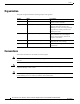
Preface Organization This guide is organized into the following chapters and appendix. Chapter Name Description Chapter 1 Chapter 1, “Product Overview” Describes the router models and the hardware features available. Chapter 2 Chapter 2, “Installing the Router” Lists the items shipped with the router, the equipment and tools necessary for installing the router, the safety warnings and guidelines, and the procedures for installing the router.
Preface Warning IMPORTANT SAFETY INSTRUCTIONS This warning symbol means danger. You are in a situation that could cause bodily injury. Before you work on any equipment, be aware of the hazards involved with electrical circuitry and be familiar with standard practices for preventing accidents. Use the statement number provided at the end of each warning to locate its translation in the translated safety warnings that accompanied this device.
Preface Avvertenza IMPORTANTI ISTRUZIONI SULLA SICUREZZA Questo simbolo di avvertenza indica un pericolo. La situazione potrebbe causare infortuni alle persone. Prima di intervenire su qualsiasi apparecchiatura, occorre essere al corrente dei pericoli relativi ai circuiti elettrici e conoscere le procedure standard per la prevenzione di incidenti. Utilizzare il numero di istruzione presente alla fine di ciascuna avvertenza per individuare le traduzioni delle avvertenze riportate in questo documento.
Preface Cisco 860 Series, Cisco 880 Series, and Cisco 890 Series Integrated Services Routers Hardware Installation Guide OL-16215-10 xi
Preface Aviso INSTRUÇÕES IMPORTANTES DE SEGURANÇA Este símbolo de aviso significa perigo. Você se encontra em uma situação em que há risco de lesões corporais. Antes de trabalhar com qualquer equipamento, esteja ciente dos riscos que envolvem os circuitos elétricos e familiarize-se com as práticas padrão de prevenção de acidentes. Use o número da declaração fornecido ao final de cada aviso para localizar sua tradução nos avisos de segurança traduzidos que acompanham o dispositivo.
Preface Cisco 860 Series, Cisco 880 Series, and Cisco 890 Series Integrated Services Routers Hardware Installation Guide OL-16215-10 xiii
Preface Warning When installing the product, please use the provided or designated connection cables/power cables/AC adaptors. Using any other cables/adaptors could cause a malfunction or a fire. Electrical Appliance and Material Safety Law prohibits the use of UL-certified cables (that have the “UL” shown on the code) for any other electrical devices than products designated by CISCO.
Preface Warning Only trained and qualified personnel should be allowed to install, replace, or service this equipment. Statement 1030 Warning Read the installation instructions before connecting the system to the power source. Statement 1004 Warning Ultimate disposal of this product should be handled according to all national laws and regulations.
Preface Searching Cisco Documents To search a HTML document using a web browser, press Ctrl-F (Windows) or Cmd-F (Apple). In most browsers, the option to search whole words only, invoke case sensitivity, or search forward and backward is also available. To search a PDF document in Adobe Reader, use the basic Find toolbar (Ctrl-F) or the Full Reader Search window (Shift-Ctrl-F). Use the Find toolbar to find words or phrases within a specific document.
CH A P T E R 1 Product Overview This chapter provides an overview of the features available for the Cisco 860 series, Cisco 880 series, and Cisco 890 series Integrated Services Routers (ISRs), and contains the following sections: • General Description, page 1-2 • Cisco 860 Series ISRs, page 1-2 • Cisco 860VAE Series ISRs, page 1-3 • Cisco 880 Series ISRs, page 1-6 • Cisco 890 Series ISRs, page 1-17 • Hardware Features, page 1-27 Note For compliance and safety information, see Regulatory Compl
Chapter 1 Product Overview General Description General Description The Cisco 860 series, Cisco 880 series, and Cisco 890 series ISRs provide data, voice, Wi-Fi CERTIFIED™ wireless access point (AP), integrated Virtual Private Network (VPN), and backup capabilities to corporate teleworkers and to remote and small offices with fewer than 20 users. These routers are capable of bridging and multiprotocol routing between LAN and WAN ports. The routers provide advanced features, such as high speed DSL (G.
Chapter 1 Product Overview Cisco 860VAE Series ISRs Figure 1-2 shows the back panel details of the Cisco 861 wireless (861W) ISR. Nonwireless routers do not have antennas on the back panel. However, the feature locations are similar for all Cisco 860 series routers.
Chapter 1 Product Overview Cisco 860VAE Series ISRs Table 1-1 Interfaces of the Cisco 860VAE Series ISRs (continued) Model Interfaces 866VAE 867VAE 866VAE-K9 867VAE-K9 1 VDSL/ADSL over POTS port — x — x 1 VDSL/ADSL over ISDN port x — x — 1. FE = Fast Ethernet 2. GE = Gigabit Ethernet Note The Cisco 866VAE, 867VAE, 866VAE-K9, and 867VAE-K9 routers each have two WAN ports. Only one of the two ports can be active at any given time.
Chapter 1 Product Overview Cisco 860VAE Series ISRs Figure 1-4 shows the back panel details of the Cisco 866VAE ISR. Figure 1-4 Back Panel of the Cisco 866VAE ISR Cisco 866VAE VDSL/ADSL WAN OVER ISDN GE0 1 2 LAN CONSOLE 12V 2.
Chapter 1 Product Overview Cisco 880 Series ISRs Cisco 880 Series ISRs The Cisco 880 series ISRs have data and voice capabilities. They have the following features: • Integrated 4-port 10/100 Ethernet switch for connecting to the LAN • 10/100 FE, VDSLoPOTS, ADSL over POTS, ADSL over ISDN, DSL Multi-mode (VDSL/ADSLoPOTS, VDSL/ADSLoISDN Cisco VA models only), or G.SHDSL port for connecting to the WAN • Optional embedded Wi-Fi CERTIFIED™, 802.
Chapter 1 Product Overview Cisco 880 Series ISRs Front Panel of the Cisco 880 Series Wireless Data Router 231950 Figure 1-6 1 1 2 2 3 LEDs 3G express card slot—Supports third-party 3G card (Cisco 880G models only) 3 USB port 1 1. See the Cisco 880 Series Integrated Services Routers data sheet for supported vendors. Figure 1-7 shows the back panel details of the Cisco 886VA data router.
Chapter 1 Product Overview Cisco 880 Series ISRs Figure 1-8 shows the back panel details of the Cisco 887VA and 886VA-M data router. Back Panel of the Cisco 887VA and 887VA-M Router 254139 Figure 1-8 1 2 3 4 5 1 Primary WAN port—VDSL/ADSL over POTS1 5 Reset button 2 4-port 10/100 Ethernet switch2 6 Power connector 3 Serial port—console or auxiliary 7 Earth ground connection 4 PoE power connector—optional 8 Kensington security slot 6 7 8 1. 887VA-M has Annex M support. 2.
Chapter 1 Product Overview Cisco 880 Series ISRs 1 ISDN port—not available on 3G models 6 PoE power connector for optional PoE module1 2 Primary WAN port2—G.SHDSL, VDSLoPOTS, ADSLoPOTS, ADSLoISDN, or 10/100 FE 7 Reset button 3 Antenna—captive omnidirectional dipole WLAN antenna (wireless models only) 8 Power connector 4 4-port 10/100 Ethernet switch 9 Earth ground connection 5 Serial port—console or auxiliary 10 Kensington security slot 1.
Chapter 1 Product Overview Cisco 880 Series ISRs Figure 1-10 shows the front panel details of the Cisco 881 SRST and Cisco 888 SRST wireless voice router.
Chapter 1 Product Overview Cisco 880 Series ISRs Figure 1-11 shows the back panel details of the Cisco 881SRST-W voice router.
Chapter 1 Product Overview Cisco 880 Series ISRs Figure 1-12 shows the back panel details of the Cisco 888SRST-W voice router. Back Panel of the Cisco C888SRST-W Voice Router 241905 Figure 1-12 2 1 2 6 3 4 5 7 8 9 10 1 Primary WAN port1—G.
Chapter 1 Product Overview Cisco 880 Series ISRs Cisco 881-V, Cisco 887VA-V, and Cisco 887VA-V-W Figure 1-13, Figure 1-14, and Figure 1-15 show the features available on the Cisco 881-V and Cisco 887VA-V routers. The features available vary, depending on the router model. Some features may not be available on your router. The Cisco 881-V and Cisco 887VA-V voice and data series gives you the flexibility to use either FXS or BRI voice ports.
Chapter 1 Product Overview Cisco 880 Series ISRs Figure 1-14 shows the back panel for the Cisco 887VA-V-W router. The Cisco 887VA-V (non-wireless) router does not have the antennas on the back panel.
Chapter 1 Product Overview Cisco 880 Series ISRs 1 Fast Ethernet WAN port 6 PoE power connector (optional) 2 Voice BRI ports 7 Reset button 3 Voice ports—four FXS/DID ports and one FXO port. 8 Power connector 4 Fast Ethernet LAN—four ports 9 Earth ground connection 5 Console Port 10 Kensington security slot Cisco 880 Series with Embedded WLAN Antennas Some Cisco 880W, 880WD, and 880-WD ISRs have three embedded WLAN antennas.
Chapter 1 Product Overview Cisco 880 Series ISRs Figure 1-17 shows the back panel details of the C887VA-WD-A-K9 and C887VA-WD-E-K9 ISRs.
Chapter 1 Product Overview Cisco 890 Series ISRs Figure 1-19 shows the back panel details of the C881WD-A-K9 and C881WD-E-K9 ISRs.
Chapter 1 Product Overview Cisco 890 Series ISRs • DIMM expansion socket that can accept up to 512 MB of additional memory, for a total of 768 MB system memory in Cisco 891 and 892 series ISRs, and a total of 1 GB system memory in Cisco 892F series ISRs • Three reverse-polarity threaded Neill-Concelman (RP-TNC) connectors on the back panel for non-captive dual-band WLAN antenna (wireless models only) • Support for the AIM2-CUE-K9 and AIM2-APPRE-104-K9 • GE small-form-factor pluggable (SFP) port (C
Chapter 1 Product Overview Cisco 890 Series ISRs Figure 1-21 shows the back panel details of the Cisco 892-W router. Nonwireless routers do not have RP-TNC antennas or connectors on the back panel. Some of the features that are shown may not be available on your router. However, the feature locations are similar across all Cisco 890 series routers.
Chapter 1 Product Overview Cisco 890 Series ISRs Figure 1-22 shows the location of the SFP port in a Cisco 892F-W router.
Chapter 1 Product Overview Cisco 890 Series ISRs Figure 1-23 shows the back panel of the Cisco 892FSP router. Figure 1-23 Back Panel of the Cisco 892FSP Router C isco 892FSP C O N SO LE GE W AN GE W AN 284781 SFP RESE T 8 9 AU X 8 12VD C 1 2 3 4 5 2.
Chapter 1 Product Overview Cisco 890 Series ISRs Figure 1-25 shows the back panel of the Cisco 896VA router. Figure 1-25 Back Panel of the Cisco 896VA Router 12 VDSL/ADSL overISDN GE WAN 0 8 1 2 6 GELAN 5 Cisco 896VA 4 CONSOLE 3 3 4 2 POE 5 1 54VDC 12VDC 0 6 1 ISDN 7 Power connector 2 GE WAN interface 8 On/Off switch 3 SFP port 9 Reset button 4 USB port RESET 1.2A 2.
Chapter 1 Product Overview Cisco 890 Series ISRs Figure 1-27 shows the back panel of the Cisco 897VA router. Figure 1-27 Back Panel of the Cisco 897VA Router 12 VDSL/ADSL overPOTS GE WAN 0 8 1 2 7 6 GELAN 5 Cisco 897VA 4 CONSOLE 3 3 2 4 POE 1 54VDC 12VDC 0 6 5 1 ISDN 7 Power connector 2 GE WAN interface 8 On/Off switch 3 SFP port 9 Reset button 4 USB port RESET 1.2A 2.
Chapter 1 Product Overview Cisco 890 Series ISRs 4 8-port Gigabit Ethernet switch1 10 Kensington security slot 5 Console / Auxiliary port 11 VDSL / ADSL over POTS 6 Power connector 1. Port 0 through 3 can be configured as POE. POE is an optional feature for this model. If this feature was not configured with the factory order, you must order and install it to enable the PoE function. Figure 1-29 shows the front panel of the Cisco 897VAM router.
Chapter 1 Product Overview Cisco 890 Series ISRs Figure 1-31 shows the front panel of the Cisco 897VAW and the Cisco 897VAMW router. Front Panel of the Cisco 897VAW and the Cisco 897VAMW Router 344770 Figure 1-31 1 1 LEDs Figure 1-32 shows the back panel of the Cisco 897VAMW router. Figure 1-32 Back Panel of the Cisco 897VAMW Router 11 VDSL/ADSL overPOTS 7 6 GELAN 5 4 8 1 3 2 3 2 POE 4 1 54VDC 12VDC 0 5 6 RESET 1.2A 2.
Chapter 1 Product Overview Cisco 890 Series ISRs Figure 1-33 shows the back panel of the Cisco 898EA router. Figure 1-33 Back Panel of the Cisco 898EA Router 7 SHDSL RJ45 ONLY 11 6 GELAN 5 Cisco 898EA 4 CONSOLE GE WAN 8 8 1 2 3 3 2 POE 1 4 AUX 0 5 54VDC 12VDC RESET 1.2A 2.
Chapter 1 Product Overview Hardware Features Hardware Features This section provides an overview of the following hardware features for the Cisco 860 series, 880 series, and 890 series ISRs. A feature summary is available at the end of this section.
Chapter 1 Product Overview Hardware Features The custom configuration file must be named one of the following: • customer-config • SN-customer-config where “SN” is the unique hardware serial number. When the system attempts to load a custom configuration file, configuration files on a USB flash drive have priority over configuration files on the router's flash drive and the “SN-customer-config” file name has priority over the “customer-config” file name.
Chapter 1 Product Overview Hardware Features To reset the router to the factory default configuration or to load a custom configuration file, follow these steps: Step 1 Turn the power on. Step 2 Press and hold the Reset button until the system status LED begins to flash. Typically, this occurs within 5 seconds. The router reloads itself after the startup configuration has been replaced with the new customer configuration.
Chapter 1 Product Overview Hardware Features LEDs The LEDs are located on the front panel of the router. Table 1-4 • Table 1-4 describes the LEDs for the Cisco 860 series, 880 series, and 890 series ISRs. • Table 1-5 lists the LED descriptions for the Cisco 866VAE, Cisco 867VAE, Cisco 866VAE-K9, and Cisco 867VAE-K9 ISRs. • Table 1-6 lists the LED description for the Cisco 892FSP ISR, 896VA, 897VA, and 898EA.
Chapter 1 Product Overview Hardware Features Table 1-4 LED Descriptions for the Cisco 860 Series, Cisco 880 Series, and Cisco 890 Series ISRs (continued) LED Color Description 860 Series 880 Series 890 Series WLAN (5 GHz) Green On—Radio is connected, SSID is configured, and client is — associated, but no data is being received or being transmitted.
Chapter 1 Product Overview Hardware Features Table 1-4 LED Descriptions for the Cisco 860 Series, Cisco 880 Series, and Cisco 890 Series ISRs (continued) LED Color Description 860 Series 880 Series 890 Series Data BRI B2 Green Blinking—B2 channel is receiving or sending data, or data is passing through ISDN channel 2. — 887, 887V, 892 888 models models 3G8 WWAN9 Green On—Service is established. — 3G models — — 3G models — Slow Blinking—Searching for service.
Chapter 1 Product Overview Hardware Features 2. LWAPP = Lightweight Access Point Protocol. 3. PPP = Point-to-Point Protocol. 4. xDSL = General term referring to various forms of DSL, including ADSL (asymmetric digital subscriber line) and VDSL (very-high-data-rate digital subscriber line). 5. DSLAM = digital subscriber line access multiplexer. 6. ATM = Asynchronous Transfer Mode. 7. EFM = Ethernet in the First Mile. 8. 3G = Third-Generation. 9. WWAN = wireless WAN. 10.
Chapter 1 Product Overview Hardware Features Table 1-5 LED Descriptions for the Cisco 866VAE, Cisco 867VAE, Cisco 866VAE-K9, and Cisco 867VAE-K9 ISRs LED Activity Description GE ACT Green On—GE WAN interface is up. Blinking—GE WAN activity (traffic in either direction). Off—Device is powered off or GE WAN interface is down. GE Mode Green On—GE WAN Mode is selected. Off—Device is powered off or DSL WAN mode is selected. 1.
Chapter 1 Product Overview Hardware Features Table 1-6 describes the LEDs for the Cisco 892FSP. Table 1-6 LED desciption for Cisco 892FSP ISR, 896VA, 897VA, and 898EA Routers LED Color Activity Description PWR_OK Green Power Status Off—No power. Steady on—Normal operation. Blink—Boot up phase or in ROM Monitor mode. GE0 Green/Amber Link Status GE1 Green On—Ethernet port is connected. Amber On—Fault with PoE. There is a fault with the inline power supply.
Chapter 1 Product Overview Hardware Features Because the LED indicators are shared, the LED illuminates (green) when either port is active. For example, the LED indicator labeled BRI 1 B1 illuminates when either the BRI1 B1 channel is active or when the FXS port is active. You can determine the activity status on each interface by using the following commands. • For activity status on the FXS ports, use the show port summary command.
Chapter 1 Product Overview Hardware Features Note Flash memory is not upgradable. An external USB flash memory module may be used if additional flash memory is needed. Main Memory Table 1-8 describes the main onboard memory storage for different router models. Table 1-8 Main Onboard Memory Storage Models Onboard Memory Storage Expandability Cisco 860 series routers 256 MB Not expandable. Cisco 860VAE series routers 256 MB Not expandable.
Chapter 1 Product Overview Hardware Features The following models have no fan: • Cisco 892FSP • Cisco 896VA • Cisco 897VA • Cisco 898EA Power Supply The Cisco 892FSP has a single +12V power supply input. The Cisco 892FSP power connector is different from the barrel-type connector on other 890 series models. The AC adapter cable connector has four pins and a built-in locking mechanism. Figure 3-27 shows the power adapter connector.
Chapter 1 Product Overview Hardware Features Wireless LAN Connectivity The embedded Wi-Fi CERTIFIED™, 802.11a/b/g/n-compliant wireless AP is preinstalled in the router as an optional feature. The Cisco 860 series routers support autonomous features and network configurations. The Cisco 880 series and 890 series routers support both autonomous and unified features and network configurations. The wireless AP does not have an external Console port.
Chapter 1 Product Overview Hardware Features Supported Cisco Radio Antennas The Cisco 891, Cisco 892, and Cisco 892F come with three removable dipole antennas that can be replaced using the Cisco approved antenna extenders listed in Table 1-11. Note Table 1-11 Cisco supports only the antennas listed in Table 1-11 with the Cisco 890 series dual-band radio module.
Chapter 1 Product Overview Hardware Features Feature Summary Table 1-12 summarizes the hardware features available in the Cisco 860 series, Cisco 880 series, and Cisco 890 series ISRs. Table 1-12 Hardware Features Available in Cisco 860 Series, Cisco 880 Series, and Cisco 890 Series ISRs Feature Description 860 Series 880 Series 890 Series Reset button Resets the router configuration to the factory default.
Chapter 1 Product Overview Hardware Features Table 1-12 Hardware Features Available in Cisco 860 Series, Cisco 880 Series, and Cisco 890 Series ISRs (continued) Feature Description 860 Series GE WAN port 10/100/1000 GE WAN Port. 866VAE, — 867VAE, 866VAE-K9, 867VAE-K9 All models VDSLoPOTS12 port Provides connection to a VDSL network. — 887V — ADSLoPOTS Provides ADSL connection over basic telephone service — with Annex A and Annex B ITU G. 992.1 (ADSL), G.992.3 (ADSL2), and G.992.5 (ADSL).
Chapter 1 Product Overview Hardware Features Table 1-12 Hardware Features Available in Cisco 860 Series, Cisco 880 Series, and Cisco 890 Series ISRs (continued) Feature Description 860 Series 880 Series Dying gasp Detects when the router is losing power, and sends a power-fail signal to warn the DSLAM16 about the impending line drop.
Chapter 1 Product Overview Hardware Features 14. G.SHDSL = (global industry standard) symmetrical high-speed DSL. 15. 3G = Third-Generation. 16. DSLAM = digital subscriber line access multiplexer. 17. SRST = Survivable Remote Site Telephony. 18. FXO = Foreign Exchange Office. 19. FXS = Foreign Exchange Station. 20. DID = Direct Inward Dialing. 21. SFP = small-form-factor pluggable.