CH A P T E R 2 Installing the Router This chapter describes the equipment and the procedures for successfully installing the Cisco 860 series, 880 series, and 890 series Integrated Services Routers (ISRs), and contains the following sections: Note • Equipment, Tools, and Connections, page 2-2 • Installing the Router, page 2-3 For compliance and safety information, see the Regulatory Compliance and Safety Information Roadmap that ships with the router and the Regulatory Compliance and Safety Informat
Chapter 2 Installing the Router Equipment, Tools, and Connections Equipment, Tools, and Connections This section describes the equipment, tools, and connections necessary for installing your Cisco 860 series, 880 series, and 890 series ISRs.
Chapter 2 Installing the Router Installing the Router – Two number-10 wood screws (round- or pan-head) with number-10 washers, or two number-10 washer-head screws, for mounting on a wall stud. The screws must be long enough to penetrate at least 3/4 in. (20 mm) into the supporting wood or metal wall stud. – Two number-10 wall anchors with washers, for mounting the router on a hollow-wall. • Wire crimper for chassis grounding.
Chapter 2 Installing the Router Installing the Router Warnings Warning This equipment needs to be grounded. Use a green and yellow 12 to 14 AWG ground wire to connect the host to earth ground during normal use. Statement 242 Warning This equipment must be grounded. Never defeat the ground conductor or operate the equipment in the absence of a suitably installed ground conductor.
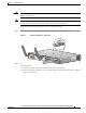
Chapter 2 Installing the Router Installing the Router Warning Note All wireless LAN products in the 5.2/5.3GHz band cannot be used outdoors. Use the product only indoors. Statement 372 Before you install the Cisco 890 series wireless router on a table, wall, or rack, connect the antennas to the back panel. It is difficult to attach the antennas after the router is installed.
Chapter 2 Installing the Router Installing the Router Antennas Oriented Vertically Up 274774 Figure 2-2 Cisco 860 Series, Cisco 880 Series, and Cisco 890 Series Integrated Services Routers Hardware Installation Guide 2-6 OL-16215-10
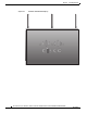
Chapter 2 Installing the Router Installing the Router Antennas Oriented Vertically Down 274775 Figure 2-3 Installing on a Table To install the router on a table or other flat horizontal surface, firmly place the router on a table or other horizontal surface. Keep at least 1 inch (2.5 cm) of clear space beside the cooling inlet and exhaust vents. Connect the chassis to a reliable earth ground.
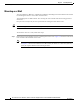
Chapter 2 Installing the Router Installing the Router Mounting on a Wall The Cisco 860 series, 880 series, and 890 series ISRs have mounting holes on the bottom of the chassis for mounting the unit on a wall or other vertical surface. The mounting holes are bidirectional. You can hang the router with the front bezel facing upward or downward. Keep at least 1 inch (2.5 cm) of clear space beside the cooling inlet and exhaust vents.
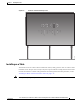
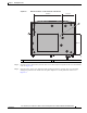
Chapter 2 Installing the Router Installing the Router Figure 2-4 Wall-mount Holes on the Underside of the Router 8.200 in. 3.673 in. 1 1 231987 5.961 in. 1 Wall-mount holes Step 2 Insert the screws, with anchors, into the wall. Leave 1/8 inch (0.32 cm) between the screw head and the wall. See Figure 2-5. Step 3 Hang the router on the screw without forcibly pushing towards the wall side. The screw head may damage the protection wall inside.
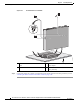
Chapter 2 Installing the Router Installing the Router Figure 2-5 Router Mounted on the Wall 1 1 4 231982 2 3 Step 4 1 Two number-10 wood screws mounted on the 3 wall 2 Wall-mount holes 4 Horizontal surface on which to place the power adapter Distance between the screw head and the wall, 1/8 in. (0.32 cm) Connect the chassis to a reliable earth ground. For the chassis ground connection procedures, see the “Installing the Router Ground Connection” section on page 2-13.
Chapter 2 Installing the Router Installing the Router Installing in a Rack The Cisco 890 series ISRs can be mounted in a rack. To install a Cisco 890 series ISR in a rack, follow these steps: Step 1 Remove the screws, as shown in Figure 2-6. Figure 2-6 Screw Locations 278159 1 1 1 Step 2 Caution Screws Using the screws provided, attach the rack-mount brackets to the Cisco 890 series ISR chassis, as shown in Figure 2-7. Use two screws on each side.
Chapter 2 Installing the Router Installing the Router Caution Warning Step 3 Chassis installation must allow unrestricted airflow for chassis cooling. To prevent bodily injury when mounting or servicing this unit in a rack, you must take special precautions to ensure that the system remains stable. The following guidelines are provided to ensure your safety: • This unit should be mounted at the bottom of the rack if it is the only unit in the rack.
Chapter 2 Installing the Router Installing the Router Installing the Router Ground Connection The router must be connected to a reliable earth ground. Install the ground wire in accordance with local electrical safety standards. • For NEC-compliant grounding, use size 14 AWG (2 mm2) or larger copper wire and a ring terminal with an inner diameter of 1/4 in. (5 to 7 mm). • For EN/IEC 60950–compliant grounding, use size 18 AWG (1 mm 2) or larger copper wire.
Chapter 2 Installing the Router Installing the Router Installing the FIPS Cover Perform the following steps to install the FIPS cover in the router: Remove the four mounting screws of the top cover.
Chapter 2 Installing the Router Installing the Router Step 2 Install the left-side FIPS cover, as shown in detail A. 284922 Detail A Adapter Plate Step 3 Rotate and bring into the close position to hinge to the correct hexagon. Step 4 Place the adapter plate before closing by aligning the mounting holes.
Chapter 2 Installing the Router Installing the Router Secure the FIPS cover with two mounting screws. Step 6 Install the right-side FIPS cover the same way as the left-side FIPS cover. Step 7 View after both covers are installed.
Chapter 2 Installing the Router Installing the Router If the FIPS covers are installed with the rack mount brackets, the adapter plates are not required in the installation.
Chapter 2 Installing the Router Installing the Router Cisco 860 Series, Cisco 880 Series, and Cisco 890 Series Integrated Services Routers Hardware Installation Guide 2-18 OL-16215-10
CH A P T E R 3 Connecting the Router This chapter describes how to connect Cisco 860 series, Cisco 880 series, and Cisco 890 series Integrated Services Routers (ISRs) to Ethernet devices, Power over Ethernet (PoE), and a network.
Chapter 3 Connecting the Router Safety Warnings Note The illustrations in this chapter show a wireless router with antennas attached. Non-wireless routers do not have antennas or antenna connectors on the back panel. However, the procedures for connecting devices to the router are the same for both wireless and non-wireless routers. Note Depending on the features available for your router, some content in this chapter may not apply to your router.
Chapter 3 Connecting the Router Safety Warnings Warning Do not use this product near water; for example, near a bath tub, wash bowl, kitchen sink or laundry tub, in a wet basement, or near a swimming pool. Statement 1035 Warning Never install telephone jacks in wet locations unless the jack is specifically designed for wet locations. Statement 1036 Warning Never touch uninsulated telephone wires or terminals unless the telephone line has been disconnected at the network interface.
Chapter 3 Connecting the Router Preparing to Connect the Router Preparing to Connect the Router Before you connect the router to the devices, install the router according to the instructions in “Installing the Router” section on page 2-1 Preventing Damage to the Router To prevent damage to your router, follow these guidelines when connecting devices to your router: • Caution Turn off power to the devices and to the router until all connections are completed.
Chapter 3 Connecting the Router Connecting a PC, Server, or Workstation Connecting a PC, Server, or Workstation To connect a PC (or other Ethernet devices) to an Ethernet switch port, follow these steps: Step 1 Connect one end of the yellow Ethernet cable to an Ethernet switch port on the router. Figure 3-1 shows a Cisco 888W router connected to a PC.
Chapter 3 Connecting the Router Connecting a Phone Connecting a Phone To connect an 802.3af-compliant phone to an Ethernet switch port, follow these steps: Note A power source must be provided for the phone to function. This can be done in two ways: the phone can be powered via the PoE function using the PoE enabled Ethernet ports, or by using an external AC power source connected to the phone. Step 1 Connect one end of the yellow Ethernet cable to Ethernet switch port 0 or port 1 on the router.
Chapter 3 Connecting the Router Connecting an External Ethernet Switch Step 2 Connect the other end of the cable to the RJ-45 port on the phone. Connecting an External Ethernet Switch If more than four PCs in an office must be connected to each other, you can add Ethernet connections to the router by connecting an external Ethernet switch to the Ethernet switch on the router.
Chapter 3 Connecting the Router Connecting the V.92 modem Port Connecting the V.92 modem Port Warning Hazardous network voltages are present in WAN ports regardless of whether power to the unit is OFF or ON. To avoid electric shock, use caution when working near WAN ports. When detaching cables, detach the end away from the unit first. Statement 1026 For dialup connection to your service provider network through the V.92 port, follow the steps given after Figure 3-4, which show this connection.
Chapter 3 Connecting the Router Connecting a Terminal or PC to the Console Port Connecting a Terminal or PC to the Console Port Connect a terminal or PC to the Console Auxiliary (Aux) port either to configure the software by using the CLI or to troubleshoot problems with the router. To connect a terminal or PC to the console port on the router and access the CLI, follow these steps: Connect the RJ-45 end of a DB-9–to–RJ-45 serial cable to the RJ-45 Console Aux port on the router.
Chapter 3 Connecting the Router Connecting a Modem to the Auxiliary Port Terminal Emulator Settings Use the following settings for the terminal emulator connection: • 9600 baud • 8 data bits, no parity • 1 stop bit • No flow control When the terminal emulator establishes communications, the router prompt is displayed. For more information on terminal emulation settings, see Applying Correct Terminal Emulator Settings for Console Connections.
Chapter 3 Connecting the Router Connecting the 3G Card Step 2 Connect the DB-9 end of the console cable to the DB-9 end of the modem adapter. Step 3 Connect the DB-25 end of the modem adapter to the modem. Step 4 Make sure that your modem and the router auxiliary port are configured for the same transmission speed (up to 115200 bits per second [b/s] is supported) and support mode control with data carrier detect (DCD) and data terminal ready (DTR).
Chapter 3 Connecting the Router Connecting the 3G Card Figure 3-7 Inserting the 3G Card 4 271473 3 2 3 1 6 5 5 1 3G card with the Cisco logo facing up 4 Screw holes for locking bracket 2 3G express card slot 5 Pin holes for aligning the locking bracket 3 Notches on the 3G card 6 SIM slot (in HSPA1 cards only) 1. HSPA = High-Speed Packet Access. Open the top of the anti-theft locking bracket, as shown in Figure 3-8.
Chapter 3 Connecting the Router Connecting the 3G Card Step 3 Slide the opened locking bracket under the 3G card. The locking bracket should align with the notches on either side of the 3G card, as shown in Figure 3-9, and the pins on the locking bracket should be inserted into the corresponding holes in the router.
Chapter 3 Connecting the Router Connecting the 3G Card Step 4 Close the locking bracket, as shown in Figure 3-10. Figure 3-10 Closing the Locking Bracket 1 271580 2 1 Step 5 2 3G card Locking bracket Insert the screws, as shown in Figure 3-11, and tighten with a number 2 Phillips screwdriver.
Chapter 3 Connecting the Router Connecting the 3G Card Note The antenna connector receptacle may be located on the left, right, or front of the 3G card, depending on your card. Figure 3-12 shows the antenna connected to the 3G card with an SSMB type plug, and Figure 3-13 shows the antenna with the SMK-TS-9 connector. Figure 3-12 Antenna connected to the 3G Card with SSMB connector 272653 1 3 2 1 Antenna on a cradle 2 Antenna SSMB connector 3 Antenna connector receptacle1 1.
Chapter 3 Connecting the Router Connecting the 3G Card Antenna with the SMK-TS- 9 Connector 279085 Figure 3-13 Original antenna assembly SMK-TS-9 connector Cable If you are using an extension cable, you must attach the 3G adapter for extended cable antenna to the body of the router. Depending on the SKU ordered, the adapters come with different connectors. Table 3-1 lists the different adapters and SKUs supported by each adapter.
Chapter 3 Connecting the Router Installing the 3G Adapter for Extended Cable/Antenna Step 8 Remove the protective tape from the adhesive on the bottom of the antenna cradle, then firmly press the cradle to the flat surface.
Chapter 3 Connecting the Router Installing the 3G Adapter for Extended Cable/Antenna Step 2 Locate the hooks on the adapter as shown in Figure 3-15. Figure 3-15 Locating the Hooks on the Adapter 279122 1 1 Step 3 Hooks on the adapter Align and insert the hooks of the adapter into the air vent holes on the left side router body as shown in Figure 3-16. Figure 3-16 Inserting the Hooks 1 1 279123 1 Hooks aligned and inserted into the router.
Chapter 3 Connecting the Router Installing the 3G Adapter for Extended Cable/Antenna Step 4 Align the circular adapter hole with the hole on the router chassis from where you removed the screw in Step 1 and use the screw to attach the adapter to the router as shown in Figure 3-17.
Chapter 3 Connecting the Router Installing the 3G Adapter for Extended Cable/Antenna Step 5 Connect the extension cable to the 3G card, as described in the “Connecting the 3G Card” section on page 3-11. The complete assembly is shown in Figure 3-18.
Chapter 3 Connecting the Router Connecting a Data BRI Port Table 3-2 Note Cisco Adapter Cables for Use with 3G Fixed Routers Cisco Product Number Antenna Adapter Length Insertion Loss Frequency (MHz) 3G-ACC-SSMB-TNC 14.5 inches 0.66 dB 2100 3G-ACC-TS9-TNC 13.5 inches 0.62 dB 2100 Antenna orientation can increase or decrease signal reception due to polarization.
Chapter 3 Connecting the Router Connecting a Data BRI Port To connect the Data BRI port to the ISDN service provider, follow these steps: Step 1 Connect one end of the orange ISDN S/T cable to the Data BRI port on the router. Figure 3-19 shows a Data BRI connection.
Chapter 3 Connecting the Router Connecting an FE Line to an FE WAN Port Connecting an FE Line to an FE WAN Port To connect the Fast Ethernet (FE) WAN port on the router, follow these steps: Step 1 Connect one end of the yellow cable to the FE WAN port as shown in Figure 3-20. Figure 3-20 Connecting the FE WAN Port 1 231992 WAN FE 4 1 2 3 Internet Step 2 1 FE WAN port 2 CAT 5 cable 3 Modem connected to the Internet Connect the other end of cable to an available port on the modem.
Chapter 3 Connecting the Router Connecting a GE Line to an GE WAN Port Connecting a GE Line to an GE WAN Port To connect the Gigabit Ethernet (GE) WAN port on the router, follow these steps: Step 1 Connect one end of the yellow cable to the GE WAN port as shown in Figure 3-21. Connecting the GE WAN Port 274493 Figure 3-21 1 2 3 Internet Step 2 1 GE WAN port 2 CAT 5 cable 3 Modem connected to the Internet Connect the other end of cable to an available port on the modem.
Chapter 3 Connecting the Router Connecting an xDSL Line Connecting an xDSL Line Warning Hazardous network voltages are present in WAN ports regardless of whether power to the unit is OFF or ON. To avoid electric shock, use caution when working near WAN ports. When detaching cables, detach the end away from the unit first. Statement 1026 Caution Cisco Systems DSL WAN Interfaces are tested for compliance with regulatory standards such as FCC Part 68, ITU-T K.21, IEC 61000-4-5, and CSA/EN/IEC/UL 60950-1.
Chapter 3 Connecting the Router Connecting an xDSL Line Figure 3-22 Primary Protection Device Location Telecom Service Overhead Service Entrance Home or Business Router Service Utilities Entrance or Demarcation Point Network Interface Box/ Network Interface Device/ Station Protector Note: Primary Protection may be located Outside or Inside of Premise Building Ground Rod connected to Service entrance and Primary Protection 281392 * Alternative Underground Service Entrance To connect the router to
Chapter 3 Connecting the Router Connecting Power over Ethernet Caution Note The primary WAN port is designed for an RJ-45 connector only. Damage to the primary WAN port may occur if a non-RJ-45 connector is inserted The DSL line must be provisioned by your service provider and correctly configured so that the LED shows the carrier detect (CD) status. On Cisco 860VAE routers, check the DSL Link LED. Connecting Power over Ethernet Warning This unit might have more than one power supply connection.
Chapter 3 Connecting the Router Connecting the AC Adapter Figure 3-24 Connecting PoE for the Cisco 880 and the Cisco 890 Series Routers 1 4 5 3 2 2 6 1 48-VDC PoE input jack 4 AC plug 2 Power cord 5 12-VDC input power-jack plug 3 Power adapter—48 VDC 6 Power adapter—12 VDC 231995 4 The Cisco 880 series ISRs with embedded WLAN antennas require a single external power supply: a 30-W power supply for non-POE-enabled routers or a 60-W power supply for POE-enabled routers.
Chapter 3 Connecting the Router Connecting the AC Adapter To connect your Cisco 860 series, Cisco 880 series, or the Cisco 890FSP ISR to an AC power outlet, follow these steps: Step 1 Connect the router to an AC power outlet as shown in Figure 3-25.To connect the Cisco 892FSP router, see Figure 3-26.
Chapter 3 Connecting the Router Connecting the AC Adapter Figure 3-26 Connecting the AC Adapter for the Cisco 892FSP 7 G E W AN 6 G E LA N 5 C isco 892FSP 4 C O N S O LE G E W AN SFP R ESET 9 8 AU X 8 12VD C 2.5A 1 2 4 343746 3 1 12-VDC plug 3 Power adapter—12 VDC 2 Power Adapter Cord 4 AC Plug Figure 3-27 Cisco 892FSP, 896VA, 897VA, and 898EA Power Adapter Connector Pin Assignment Pin 4 Pin 2 284800 Pin 3 Pin 1 Pin 1 Ground Pin 3 +12 V Pin 2 1 Pin 4 NC NC 1.
Chapter 3 Connecting the Router Connecting the AC Adapter Step 2 To secure the power cord to the router, attach the power lock clip to the power cord, slide the clip to the end of the DC plug, and secure the retaining clip into the router chassis. See Figure 3-28.
Chapter 3 Connecting the Router Connecting an FXS Line Step 3 Snap the latches into the holes on either side of the power connector. See Figure 3-29. Figure 3-29 Power Lock Clip Latched Into the Holes on Either Side of the Power Connector 1 4 3 Note 270800 2 1 Power lock clip 3 Power adapter 2 Power cord 4 AC plug Figure 3-26 shows how to connect the AC power outlet for the Cisco 892FSP.
Chapter 3 Connecting the Router Connecting an FXS Line Warning For connections outside the building where the equipment is installed, the following ports must be connected through an approved network termination unit with integral circuit protection: FXS. Statement 1044 To connect the FXS line, follow these steps: Step 1 Connect one end of the straight-through RJ-11 cable to the FXS port. Figure 3-30 shows an FXS line connection.
Chapter 3 Connecting the Router Connecting an FXO Line Connecting an FXO Line Use a straight-through RJ-11 cable to connect the FXO voice port to the PSTN or PBX through a telephone wall outlet. Warning Hazardous network voltages are present in WAN ports regardless of whether power to the unit is OFF or ON. To avoid electric shock, use caution when working near WAN ports. When detaching cables, detach the end away from the unit first.
Chapter 3 Connecting the Router Connecting a Voice ISDN BRI Line Note If you have specified the use of a private line automatic ringdown (PLAR) off-premises extension (OPX) connection mode for an FXO voice port (with loop resistance less than 8000 Ohm), you must ensure that the soft-offhook option is enabled on the port.
Chapter 3 Connecting the Router Connecting a Voice ISDN BRI Line Figure 3-32 shows a voice BRI line connection. Figure 3-32 Connecting a Voice BRI Line 1 2 241906 3 Step 2 1 Voice BRI port 2 RJ-45 cable 3 Telephone outlet Connect the other end of the cable to the RJ-45 telephone outlet or other device.
Chapter 3 Connecting the Router Connecting a Small Form-Factor Pluggable Module Connecting a Small Form-Factor Pluggable Module This section describes how to connect and remove a small form-factor (SFP) module and contains the following information: • Safety Warnings, page 3-37 • Installing an SFP Module, page 3-38 • Removing an SFP Module, page 3-38 • Online Insertion and Removal, page 3-39 Safety Warnings Laser Safety Warnings Optical SFPs use a small laser to generate the fiber-optic signal.
Chapter 3 Connecting the Router Connecting a Small Form-Factor Pluggable Module Installing an SFP Module To connect and secure the SFP module, follow these steps: Step 1 Tip Slide the SFP into the SFP port connector until it locks into position (see Figure 3-33). If the SFP uses a bale-clasp latch (see Figure 3-33), the handle should be on top of the SFP module.
Chapter 3 Connecting the Router Connecting a Small Form-Factor Pluggable Module Figure 3-34 Figure 5-42 Disconnecting SFP Latch Mechanisms 1 2 3 4 A 117722 B Tip Step 3 1 Sliding latch 3 Bale-clasp latch 2 Swing and slide latch 4 Plastic collar latch Use a pen, screwdriver, or other small straight tool to gently release a bale-clasp handle if you cannot reach it with your fingers. Grasp the SFP on both sides and remove it from the router.
Chapter 3 Connecting the Router Verifying Connections Verifying Connections To verify that all devices are properly connected to the router, first turn on all the connected devices, then check the LEDs. To verify router operation, refer to Table 3-3. For the full LED descriptions, see the “LEDs” section on page 1-30. Table 3-3 Verifying the Router Operation Power and Link LEDs to Check Normal Patterns Power OK On when power is supplied to the router.
Chapter 3 Connecting the Router Verifying Connections Table 3-3 Verifying the Router Operation (continued) Power and Link LEDs to Check Normal Patterns To wireless LAN WLAN LINK Wireless LAN link status: WLAN 2.4 GHz WLAN 5.0 GHz PoE14 PoE 0 (880 and 890 series only) PoE 1 (880 and 890 series only) • Green if at least one client is associated. • Off if no client is associated. Wireless LAN 2.
Chapter 3 Connecting the Router Verifying Connections Table 3-3 Verifying the Router Operation (continued) Power and Link LEDs to Check Normal Patterns To DSL line (860VAE models only) DSL LINK On when DSL WAN mode is selected and DSL training complete. Blinking when DSL WAN mode is selected but incomplete DSL LinkUp state such as in-training (slow initially, fast when almost connected), or controller "OFF", or no cable attached to DSL connector.
CH A P T E R 4 Initial Configuration This chapter provides instructions for initial configuration of the Cisco 860 series, 880 series, and 890 series Integrated Services Routers (ISRs). For the initial configuration, we recommend using Cisco Configuration Professional (CP) Express. Cisco CP Express is a web-based graphical user interface that guides you through initial configuration.
Chapter 4 Initial Configuration Cisco IOS CLI To configure the initial router settings using the Cisco IOS CLI, follow these steps: Step 1 Set up a console connection to your router. The following message is displayed: ... router con0 is now available Step 2 Press Return. The following message is displayed: Cisco Configuration Professional Express (Cisco CP Express) is installed on this device. This feature requires the one-time use of the username "username1" with the password "password1.
Chapter 4 Initial Configuration Setup Command Facility Note Step 7 Save your configuration changes regularly to avoid losing them during resets, power cycles, or power outages. Use the copy running-config startup-config command at the privileged EXEC mode prompt (Router#) to save the configuration to NVRAM. Verify the initial configuration. See the “Verifying the Initial Configuration” section on page 4-5.
Chapter 4 Initial Configuration Setup Command Facility Step 4 When the following messages appear, enter yes to enter basic management setup. At any point you may enter a question mark '?' for help. Use ctrl-c to abort configuration dialog at any prompt. Default settings are in square brackets '[]'.
Chapter 4 Initial Configuration Verifying the Initial Configuration The configuration is displayed: The following configuration command script was created: hostname Router enable secret 5 $1$D5P6$PYx41/lQIASK.HcSbfO5q1 enable password xxxxxx line vty 0 4 password xxxxxx snmp-server community public ! no ip routing ! interface FastEthernet4 no shutdown speed 100 duplex auto ip address 172.1.2.3 255.255.0.0 ! Step 12 Respond to the following prompts. Enter 2 to save the initial configuration.
Chapter 4 Initial Configuration Initial Configuration of the Wireless Access Point Initial Configuration of the Wireless Access Point The embedded wireless access point (AP) runs its own IOS.
A P P E N D I X A Technical Specifications This appendix provides router, port, and cabling specifications for the Cisco 860 series, Cisco 880 series, and Cisco 890 series Integrated Services Routers (ISRs).
Appendix A Technical Specifications Router Specifications Router Specifications Table A-1 lists the system specifications for the routers. Table A-1 Router Specifications Design Specification (all models except Cisco 860VAE series) Design Specification Cisco 860VAE series Dimensions with antenna and rubber feet (H x W x D) 1.9 x 12.8 x 10.4 in. 1.75 x 9.5 x 9 in. Weight (not including desktop power supply) 5.5 lb (2.5 kg), maximum 3 lb (1.
Appendix A Technical Specifications Wireless Access Point Wireless Access Point Table A-2 lists the specifications for the wireless access point (AP). Table A-2 Wireless Access Point Specifications Description Design Specification Radio technology IEEE 802.11n draft 2.0 standard compliant. 2x3 MIMO1 radio. Backward compatible with 802.11b/g and 802.11a (Cisco 890 series routers). Operating frequency Cisco 860 series and 880 series ISRs 2.4-GHz radio band Cisco 890 series ISRs 2.
Appendix A Technical Specifications Console and Auxiliary Port Connector Pinouts 1. RX = Receive 2. TX = Transmit Table A-4 describes the RJ-45 connector pinouts for the Gigabit Ethernet (GE) ports of the Cisco 860VAE and 860VAE-K9 ISRs. Table A-4 Ethernet GE Port Pinouts Pin GE Signal (LAN and WAN) 1 Tx A+1 2 Tx A- 3 Rx B+2 4 Tx C+ 5 Tx C- 6 Rx B- 7 Rx D+ 8 Rx D- 1. TX = Transmit 2.
Appendix A Technical Specifications FXS and FXO Port Connector Pinouts FXS and FXO Port Connector Pinouts Table A-6 lists the FXS and FXO connector pinouts. Table A-6 FXS and FXO Connector Pinouts (RJ-11-to-RJ-45) Pin Signal 1 NC 2 NC 3 TIP 4 RING 5 NC 6 NC VDSL2 Port Connector Pinouts Table A-7 lists the VDSL2 connector pinouts.
Appendix A Technical Specifications V.92 Port Connector Pinouts V.92 Port Connector Pinouts Table A-9 lists the V.92 connector pinouts. Table A-9 V.92 Connector Pinouts (RJ-11-to-RJ-45) RJ-11 Pin Function 1 Unused 2 Unused 3 TIP 4 RING 5 Unused 6 Unused G.SHDSL Port Connector Pinouts Table A-10 lists the pinouts for the symmetrical high-speed DSL (G.SHDSL) WAN port for two-pair products, including the following router model(s): • C888 Table A-10 G.
Appendix A Technical Specifications Data BRI Port Connector Pinouts Table A-11 G.SHDSL WAN Port Pinouts for Four-Pair Products (continued) Pin Function 4 TIP (Port0) 5 RING (Port0) 6 RING (Port2) 7 TIP (Port3) 8 RING (Port3) Data BRI Port Connector Pinouts Table A-12 lists the pinouts for the Data BRI port.
Appendix A Technical Specifications SFP Port Connector Pinouts SFP Port Connector Pinouts Table A-14 lists the pinouts for the SFP port.
Appendix A Technical Specifications Cable Specifications Ethernet Cable Specifications Table A-15 lists the specifications that apply to both straight-through and crossover Ethernet cables. Table A-15 Ethernet Cable Specifications Type Category 10BASE-T Category 3 or 5 100BASE-T Category 5 or higher 1000BASE-T Category 5 or higher Maximum Cable Length The maximum length for the Ethernet cables that connect equipment to the router is 328 feet (100 meters).
Appendix A Technical Specifications Cable Specifications Cisco 860 Series, Cisco 880 Series, and Cisco 890 Series Integrated Services Routers Hardware Installation Guide A-10 OL-16215-10