■ chapter 1 getting to know the basics C H A P T E R ▼ O N E GETTING TO KNOW THE BASICS This chapter introduces the features and components of the computer.
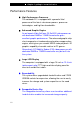
■ chapter 1 getting to know the basics Performance Features High Performance Processor The notebook PC is equipped with a powerful Intel processor of the latest sub-micron process, processor technologies, and high bus bandwidths. Advanced Graphic Engine An on-board nVidia GeForce FX Go5600 video processor with dedicated 64MB or 128MB frame buffer gives excellent graphic performance.
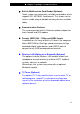
■ chapter 1 getting to know the basics Built-in Multifunction Card Reader (Optional) Some system may come with a multiple card reader, which supports SD, MS, MMC Card formats. This allows user to access a wide array of portable memory devices available today. Communication Features The system provides built-in Ethernet network adapter for local network and 56K modem. Firewire (IEEE1394 / 1394a) and USB2.
■ chapter 1 getting to know the basics Adding a Mini-PCI Type Wireless LAN Card (Optional Device ) Your computer comes with a unique Mini PCI Card socket, which is located next to the DRAM socket and inside the DRAM door. The socket allows the computer to add unique features such as wireless LAN (IEEE802.11b). Ask your dealer for information on installation and the availability of the mini PCI card.
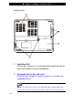
■ chapter 1 getting to know the basics Bottom View 1. Ventilation Grill The fan grill is where air is exchanged to dissipate the internal heat. Do not block this airway completely. 2. Swappable Device Bay and Latch Push the latch and pull on the drive hard case to remove the swappable device. Note: The optical drive resides in the Swappable Device Bay. Additionally, you may also purchase an optional hard drive module to be used in this bay.
■ chapter 1 getting to know the basics 3. Hard Disk Drive This is the system’s hard drive module. The hard disk drive stores all the system data. The hard disk drive can be upgraded to a larger capacity. (See Chapter 4 for instructions on a hard drive upgrade.) 4. Battery Pack and Battery Latch The battery pack is a built-in power source for the notebook. Slide the battery latch to release the battery pack.
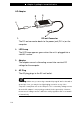
■ chapter 1 getting to know the basics AC Adapter 1. DC-out Connector The DC-out connector docks to the power jack (DC-in) on the computer. 2. LED Lamp The LED lamp appears green when the unit is plugged into a valid AC source. 3. Adapter The adapter converts alternating current into constant DC voltage for the computer. 4. AC Plug The AC plug plugs to the AC wall outlet. Warning: Make sure you are using a standard 3-prong AC wall socket with a ground pin.
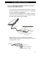
■ chapter 1 getting to know the basics TV Tuner / Video Capturing Module and Video / Audio Input Breakout Cable (Optional Device) Your system may a video-capturing module built-in. To record or watch TV programs, connect the external TV Tuner Module to the TV Tuner port on the notebook. If the device driver and application have not been installed to your system, you may need to do so via the factory CD-ROM disc when you first power up the notebook.
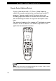
■ chapter 1 getting to know the basics Remote Control (Optional Device) If your system comes with a TV Tuner / Video Capturing module, the remote control can be used to play or record TV programs. You may need to install the device driver and recording application before the remote control can be used. See the following illustration for a general description of the keys.
■ chapter 1 getting to know the basics How to Use the Romote, Watch TV and Record Video Clips The following is a brief guide. You need to install the card’s driver and recording application from PixelView’s installation CD-ROM disk. You need to install a utility program called TV Card or PixelView in order to use the card’s function. Connect a video source, cable, or antenna to the TV Tuner Module. The TV Tuner Module is either NTSC or PAL compliant. The recorded video clip is in .AVI format.
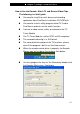
■ chapter 1 getting to know the basics You may need to make sure that the TV Card is set to the correct region for it to tune-in accurately. Go to [Start > Programs > TV Card > SW Configuration]. See below. Press TV button on the remote and the PixelView TV Card application will start. Or, simply go to [Start > Programs > TV Card > TV Card] to launch the application. See below.
■ chapter 1 getting to know the basics If you are running TV Card application the first time, press TV setup button on the PixelView video panel to scan all available channels. Note: For additional information regarding the TV viewing, recording, and remote control operations, please consult the Help Menu in the application and/or additional literature.
■ chapter 1 getting to know the basics LED Status Indicator The LED Status Indicator displays the operating status of your notebook. When a certain function is enabled, an LED will light up. The following section describes its indication. System Status Indicator LED Graphic Symbol Indication Green light indicates the hard drive is being accessed. Green light indicates the optical drive is being accessed. Green light indicates the numeric keypad is activated.
■ chapter 1 getting to know the basics Power Indicator LED Graphic Symbol Indication Persistent green light indicates Power On. Light-off indicates the notebook is in Power Off mode. Blinking green light indicates the battery power is currently low. Blinking orange light indicates the battery is being charged (the system is OFF.) Blinking orange light indicates the battery is being charged (the system is ON.
■ chapter 1 getting to know the basics Keyboard Features Function Keys (Quick Keys) Graphic Symbol Action System Control Fn + F1 Enters Suspend Mode. Fn + F3 Turns Battery Warning Beep on or off. Fn + F4 Changes Display Mode: LCD-only, CRT-only and LCD&CRT. Fn + F5 Turns Speaker Volume up. Fn + F6 Turns Speaker Volume down. Fn + F7 Increases Display Brightness. Fn + F8 Decreases Display Brightness. Num Lock Enables the embedded keypad to work in numeric mode.
■ chapter 1 getting to know the basics Windows Keys Your keyboard also has two Windows keys: 1. Start Key This key allows you to pull up the Windows Start Menu at the bottom of the taskbar. 2. Application Menu Key This key brings up the popup menu for the application, similar to a click of the right mouse button. Embedded Numeric Keypad Press Num Lock to enable the embedded numeric keypad. The numbers are printed in upper right corner of a key, in a color different from the alphabets.
■ chapter 1 getting to know the basics Touch Pad with Page Up / Page Down Function The built-in touch pad, which is a PS/2-compatible pointing device, senses movement on its surface. As you move your fingertip on the surface of the pad, the cursor responds accordingly. The following items teach you how to use the touch pad: 1. Move your finger across the touch pad to move the cursor. 2. Press buttons to select or execute functions. These two buttons are similar to the left and right buttons on a mouse.
■ chapter 1 getting to know the basics Graphic Subsystem Your computer uses a high performance 16-inch or 15.4-inch (wide aspect ratio) active matrix TFT panel with high resolution and multi-million colors for comfortable viewing. The nVidia GeForce FX Go5600 or ATI Mobility Radeon 9?00 video graphics accelerator, which is Microsoft DirectX 9 compatible, performs graphic rendering at a lighting-fast speed.
■ chapter 1 getting to know the basics Opening and Closing the Display Panel To open the display, slide the LCD latch to the right and lift up the lid. Then tilt it to a comfortable viewing position. To close the display cover, fold it down gently until the LCD latches click into place. Warning: To avoid damaging the display, do not slam it when closing.
■ chapter 1 getting to know the basics Audio Subsystem Your computer’s audio subsystem is Sound Blaster Pro-compatible. Adjusting the Volume Manually To increase the volume, press Fn+ F5. To decrease the volume, press Fn+F6. Adjusting the Audio Volume in Windows 1. Click the speaker symbol in the task tray in Windows. 2. Drag the volume control bar up or down to adjust the volume. 3. To temporarily silence the speaker without changing the volume setting, click Mute.
■ chapter 1 getting to know the basics Modem Your computer comes with a 56K V.90 internal fax/modem and a phone jack (RJ-11), which is located on the right rear side of your computer. Use a telephone cable to connect the computer to the telephone wall outlet. Connecting the Modem 1. Plug one end of the phone line into the modem port located on the rear side of the computer. (For EMI compliance, you need to clip the included EMI CORE to the phone line.) 2.
■ chapter 1 getting to know the basics Ethernet Your computer is equipped with a 10/100Base-TX Fast Ethernet network adapter. Connect the active LAN cable to the RJ-45 LAN port located on the left rear side of the computer. This allows you to access and transmit data in the local area network. Connecting to the Network Use Unshielded Twisted Pair (UTP) Ethernet cable only. 1. Insert one end of the UTP cable into the network connector until the connector snaps securely into the receptacle. 2.
■ chapter 2 bios setup and security feature C H A P T E R ▼ T W O BIOS SETUP AND SECURITY FEATURE In this chapter, you will learn how to enter the BIOS Setup Menu and manipulate various hardware control settings. You will also learn how to use the built-in security features.
■ chapter 2 bios setup and security feature The Setup Utility is a hardware configuration program built into your computer’s BIOS (Basic Input/Output System). It runs and maintains a variety of hardware functions. It is a menu-driven software, which allows you to easily configure and change the settings. The BIOS contains manufacture’s default settings for the computer’s standard operations. However, there are occasions when you may be required to modify the default settings in the BIOS.
■ chapter 2 bios setup and security feature Entering the BIOS Setup Screen First turn on the power. When the BIOS performs the POST (Power-On Self Test), press Del key quickly to activate the AMI BIOS Setup Utility. Note: You may need to press F2 key fairly quickly. Once the system begins to load Windows, you may have to retry by cycle-power on again Leaving the BIOS Setup Screen When you have finished modifying the BIOS settings, exit the BIOS. It takes a few seconds to record changes in the CMOS.
■ chapter 2 bios setup and security feature Modifying the BIOS Settings The AMIBIOS setup main menu is subdivided into sub-menus. Each menu item is described in this section. Main Setup Under this menu, you may change time/date and view basic processor and system memory information. Item Date Selections / Sub-menu N/A Time N/A Description Type in the current date, in MM/DD/YY format. Type in the current date, in HH:MM:SS format.
■ chapter 2 bios setup and security feature Auto ARMD ATAPI CDROM Not Installed Primary IDE Master Secondary IDE Master Primary Master is where BIOS tries to boot from first. The primary master controls the hard drive. Normally, Auto is selected. The secondary master controls the ATAPI CD-ROM drive. Normally, Auto is selected.
■ chapter 2 bios setup and security feature Normally use Auto To let BIOS decide the PIO mode setting. If the selected PIO mode is not supported by the IDE drive, the hard disk drive may not work properly. S.M.A.R.T. Mode: Self-diagnostic and self-monitoring features are built into newer type hard drive. Select Auto to enable S.M.A.R.T. DMA Mode: The hard drive in your computer support Ultra DMA mode. Block Multi-Sector Transfer: The hard drive in your computer support Multi-sector data Transfer.
■ chapter 2 bios setup and security feature Note: If you select NSC DP83815/83816MacPhyter, the system will attempt to boot from the network. Note: When the BIOS performs POST, you may also press F8 Key to enable the Boot Device selection menu. You may choose ATAPI CDROM, Hard Drive, or NSC MacPhyter as the first storage device to boot from. If you have already connected a USB Floppy Disk Drive before powering up, it will appear as a Removable Device in the Boot Device selection menu.
■ chapter 2 bios setup and security feature Note: About Boot Sector Virus Protection: If enabled, the following warning message appears when a program attempts to alter the boot sector. You may have to enter “N” several times to prevent the boot sector write. Boot Sector Write!!! Possible VIRUS: Continue (Y/N)? _ The following warning message appears when a program attempts to format the hard disk drive.
■ chapter 2 bios setup and security feature Note: The Suspend Mode selection in BIOS only applies to older Windows version (such as Windows 3.1 or Windows 95 or NT4) or non-Windows operating system. In Windows ME / 98SE / 2000 / XP, suspend mode and settings are determined by settings in the Power Options Properties (Start > Control Panel > Power Options).
■ chapter 3 battery power & power management C H A P T E R ▼ T H R E E BATTERY POWER & POWER MANAGEMENT In this chapter, you will learn the fundamentals of power management and how to use it to achieve longer battery life.
■ chapter 3 battery power & power management In this chapter, you will learn how to operate your notebook on battery power, how to handle and maintain the battery pack, and learn about the system’s power saving features. TFT display, central processor, hard disk drive are the major hardware subsystems that consume the most power. Power management deals how these key components should behave to conserve power.
■ chapter 3 battery power & power management Battery Low-Power Warning 1. Low Battery Warning Low battery condition occurs when battery power is reduced to 6%. The green power LED indicator blinks and the system beeps once every 16 seconds or so. 2. Very Low Battery Warning Very Low battery condition occurs at 3 % power remaining. The power LED indicator blinks and the system beeps at 4-second interval.
■ chapter 3 battery power & power management Installing and Removing the Battery Pack Note: The system is not designed for frequent battery pack removal. When you need to remove the battery pack, please observe the following steps. To Remove the Battery Pack: 1. Place the notebook bottom-side up on a flat and secured surface. 2. Push the latch and pull the battery’s hard case away from the notebook.
■ chapter 3 battery power & power management To Install the Battery Pack: 1. Place the notebook bottom-side up on a flat and secured surface. 2. Carefully insert the battery pack into the battery compartment of the notebook. Charging the Battery and Charging Time To charge the battery, while the battery pack is in the notebook, plug the AC adapter into the notebook and an electrical outlet. The charging time is approximately 3~4.
■ chapter 3 battery power & power management Checking the Battery Level You can check the remaining battery power in the Windows battery status indicator, which is located at the lower right-hand corner of the task bar. (If you do not see a battery or AC-in icon on the task tray, go to Power Options Properties box and click on the Advanced tab. Check off ``Always show icon on the task bar``.) Alternatively, you can access the power meter by clicking the Power Options icon in the Windows Control Panel.
■ chapter 3 battery power & power management Using Windows Power Options Windows Power Management provides basic power saving features. In the Windows Power Options Properties [Start > Settings > Control Panel > Power Options] dialogue box, you may enter time-out values for display and hard disk drive. Windows power manager saves power by turning off hard drive after 1 minute of inactivity, for example.
■ chapter 3 battery power & power management In this dialog box, you can manually set the LCD and hard drive’s time-out values in the Plugged in column and in the Running on batteries column. Lower time-out values will save more battery power. Note: Also consult Windows user guide for more information on how to use Windows power management functions. Note: Actual dialogue box shown above may appear slightly different.
■ chapter 3 battery power & power management Suspend Mode Standby Suspend The system automatically enters this mode after a period of inactivity, which is set in the Power Schemes dialog box. In Standby mode, hardware devices, such as display panel and hard disk, are turned off to conserve energy. Hibernate Suspend In this mode, all system data are saved in the hard disk before powering down.
■ chapter 3 battery power & power management Note: Do not install or remove the memory module when the system is in the suspend mode. Note: Actual dialogue box shown above may appear slightly different.
■ chapter 3 battery power & power management Power Button Action The notebook PC’s power button can be set to turn off the system or activate the suspend mode. Go to [Start > Settings > Control Panel > Power Options] and click on the Advanced tab. In the pull-down menu, select how you wish the power button to work as. Note: Actual dialogue box shown above may appear slightly different.
■ chapter 3 battery power & power management Low Battery Warning You can define when and how the system warns you of its battery-low condition. Go to the Alarms tab in the Power Options Properties box. If you wish to hear audible beeps, click on the Alarm Action button and put a check on Sound Alarm. Note: Consult Windows user guide for more information on how to use Windows power management functions. Note: Actual dialogue box shown above may appear slightly different.
■ chapter 3 battery power & power management Power Manu Quick Access Instead of making specific selections in the Power Options Properties box, you can quickly and easily specify which pre-set power saving function you desire by clicking on the Battery icon at the lower right-hand corner of the task bar. (If you do not see a battery or AC-in icon, go to Power Options Properties box and click on the Advanced tab. Check off ``Always show icon on the task bar``.
■ chapter 4 upgrading your computer C H A P T E R ▼ F O U R UPGRADING YOUR COMPUTER In this chapter, you will learn how to upgrade the DRAM, hard disk drive, and to install the optional wireless LAN mini PCI card.
■ chapter 4 upgrading your computer Upgrading the Hard Disk Drive Replacing the original drive with one of larger capacity can increase the hard drive capacity of your computer. The computer uses a 9.5 mm (height), 2.5-inch Ultra ATA-66 / 100 / 133 type hard disk. Be sure to make a backup copy of all your data before attempting this operation. Warning: Hard drive upgrade is a delicate process. Please observe the following instructions carefully or have a qualified technician install it for you.
■ chapter 4 upgrading your computer Upgrading the Hard Disk Drive To replace the hard disk drive, do the following: 1. Turn OFF the computer. Unhook the AC cord and all cables/devices attached to the notebook. 2. Place your hand on a large metal object momentarily to discharge any static electricity. 3. Locate and remove 2 Screw A’s on the Metal Cover. Screw A x2 Metal C over 4. 5. Remove the Metal Cover. Locate and remove 4 Screw B’s. Gently remove the HDD module from the HDD cable connector.
■ chapter 4 upgrading your computer 6. Locate and remove 4 Screw C’s from the HDD module. Remove the metal case. Screw C x2 Metal Cover Screw C x2 7. Re-attach the metal cover to the new hard drive and tighten 4 Screw C’s. Note the green PC board of the hard disk drive is facing against the metal case. 8. Re-attach the HDD Cable Connector to the HDD module. 9. Re-attach and tighten 4 Screw B’s. (If the HDD assembly is not fully inserted into the bay, the screw and its hole will not line up.) 10.
■ chapter 4 upgrading your computer Upgrading the System Memory Many applications will generally run faster when the computer’s dynamic memory capacity is increased. The computer provides one DDR memory socket, located underneath the System Device Cover. You can increase the amount of memory by replacing the existing one with a dual inline memory module (commonly known as DIMM) of a higher capacity. The DIMM can be 128MB, 256MB, 512MB, or 1024MB in capacity.
■ chapter 4 upgrading your computer Installing a memory module (DIMM) into the system To install the DIMM, do the following: 1. Power OFF the notebook. Unplug the AC cord and all cables/devices attached to the notebook. 2. Place your hand on a large metal object momentarily to discharge any static electricity. Place the notebook on a flat surface and fully open the LCD lid. 3. Find the keyboard latches near the upper edge of the keyboard. Latch A Latch A 4. The latch is spring-loaded.
■ chapter 4 upgrading your computer Metal Cover Screw A x3 Metal Cover 6. Remove 3 Screw A’s and remove the DIMM Metal Cover. The DIMM socket is now seen as shown below. DIMM Socket x2 7. If you need to remove an old DIMM from the socket, press out on the latches located on both edges of the socket at the same time. The DIMM should pop up to an angle of 30 degree (see diagram below.). Pull the DIMM module out of the memory socket. Store away the DIMM for the future use.
■ chapter 4 upgrading your computer 8. Install the new DIMM module into the memory socket. The DIMM will only fit in one orientation. Insert the DIMM at an angle of approximately 30 degrees into the empty memory socket. Then press it firmly so that the contact edge is driven into the receiving socket. Notch 9. Pivot the DIMM until the latches on both sides of the socket snap into place. Note: Notice the notch on the DIMM. The notches should fit nicely with the socket. 10.
■ chapter 5 trouble shooting C H A P T E R ▼ F I V E TROUBLE SHOOTING In this chapter, you will learn how to solve common hardware and software problems.
■ chapter 5 trouble shooting Your computer has been fully tested and complies with the system specifications before shipping. However, incorrect operations and/or mishandling may cause problems. This chapter provides a reference for identifying and correcting common hardware and software problems that you may encounter. When you encounter a problem, you should first try to go through the recommendations in this chapter.
■ chapter 5 trouble shooting hardware devices in the BIOS Setup utility. A faulty setting may cause the system to misbehave. If you are not sure of the changes you made, try to restore all the settings to factory defaults. Be sure all the device drivers are installed properly. For example, without the audio driver properly installed, the speakers and microphone will not work.
■ chapter 5 trouble shooting Audio Problems No speaker output Turn up the volume dial located at the right edge of the computer. See Chapter 1 for its location. Software volume control is turned down in Microsoft Sound System or is muted. Double-click the speaker icon on the lower right corner of the taskbar to see if the speaker has been muted or turned down all the way. Most audio problems are software-related. If your computer worked before, chances are software may have been set incorrectly.
■ chapter 5 trouble shooting Hard Disk Problems The hard disk drive does not work or is not recognizable If you had just performed a hard disk upgrade, make sure the hard drive connector is not loose and the hard disk drive is also correctly seated. Remove it and reinsert it firmly, and restart your PC. (Refer to Chapter 4 for details.) The new HDD may need to be partitioned and reformatted. O/S and drivers will need to be re-installed as well. Check the hard disk indicator LED.
■ chapter 5 trouble shooting for instructions on decreasing the cache size or on removing temporary Internet files. Empty the Recycle Bin to create more disk space. When you delete files, Windows saves them to the Recycle Bin. The hard disk takes longer to read a file If you have been using the drive for a period, the files may be fragmented. Go to [Start > Programs > Accessories > System Tools > Disk Defragmenter] to perform a disk defragmentation. This operation may take a while.
■ chapter 5 trouble shooting CD-ROM, DVD-ROM, CD-RW, or Combo Drive Problems The CD-ROM, DVD-ROM, or Combo drive does not work Try rebooting the system. The disk is damaged or files are not readable. After you have inserted a CD-ROM disk, it may take a moment before you can access its content. The drive dose not read any disks The CD may not be properly seated in the tray. Make sure the disk is firmly seated onto the spindle. The disk is damaged or not readable.
■ chapter 5 trouble shooting Display Problems The display panel is blank when the system is turned on Make sure the computer is not in the Standby or Hibernate suspend modes. The display is turned off to conserve energy in these modes. The screen is difficult to read The display resolution should at least be set to at least1024x768 for optimal viewing. 1. Go to [Start > Settings > Control Panel] and double-click the Display icon. 2.
■ chapter 5 trouble shooting Keyboard and Mouse Problems The built-in touch pad performs erratically Make sure there is no excess perspiration or humidity on your hand when using the touch pad. Keep the surface of the touch pad clean and dry. Do not rest your palm or wrist on the surface of the touch pad while typing or using the touch pad. The built-in keyboard accepts no input If you are connecting an external keyboard to the system, the built-in keyboard may not work. Try restarting the system.
■ chapter 5 trouble shooting CMOS Battery Problem A message “CMOS Checksum Failure” displays during the booting process or the time (clock) resets when booting Try to reboot the system. If the message “CMOS Checksum Failure” appears during the booting procedure even after rebooting, it may indicate failure of the CMOS battery. If so, you need to replace the battery. This battery normally lasts two to five years. The battery is of type CR2032 (3V). You may replace it by yourself.
■ chapter 5 trouble shooting Memory Problems The POST does not show an increased memory capacity when you have already installed additional memory Certain brands of memory module may not be compatible with your system. You should ask your vendor for a list of compatible DIMM. The memory module may not be installed properly. Go back to Chapter 4 to review the details of this operation. The memory module may be defective.
■ chapter 5 trouble shooting Modem Problems The built-in modem does not respond Make sure the modem driver is loaded properly. Go to [Start > Settings > Control Panel > Phone and Modem Options] and go to Modems tab. Make sure SmartLink 56K Voice Modem or Uniwill V.90 Modem is listed. Otherwise, click the Add button to add the modem drive, which is located in the factory CD-ROM (or floppy diskette).
■ chapter 5 trouble shooting Network Adapter / Ethernet Problems The Ethernet adapter does not work Go to [Start > Settings > Control Panel > System > Hardware > Device Manager]. Double-click on Network Adapters and check if SiS 900-Based PCI Fast Ethernet Adapter appears as one of the adapters. If it does not exist, Windows has not detected the National Semiconductor Fast Ethernet adapter or the device driver has not been installed properly.
■ chapter 5 trouble shooting PC Card / PCMCIA Problems Note: Some system may not have the PC Card Slot option. PC Cards do not functionMake sure you have properly installed the driver for the card. Consult the card’s manual or contact the vendor for trouble-shooting. The PC card cannot be recognized Windows NT4.0 does not support PCMCIA (PC Card) function. You may need an external program for this. Make sure the card is fully inserted; the outer end of the card should be even with the edge of the computer.
■ chapter 5 trouble shooting Performance Problems The computer becomes hot In a 35oC environment, the certain areas of the computer’s back case are expected to reach 50 degrees. Make sure the air vents are not blocked. If the fan does not seem to be working at high temperature (50 degrees Celsius and up), contact the service center.
■ chapter 5 trouble shooting Printer Problems The printer does not print Make sure the cable connection is secured and the printer is powered up, if the printer is connected via the parallel port. Run the printer self-test to see if it reports any problem. Check if the printer displays any error messages. A paper jam may have occurred. Make sure you have already installed the printer driver. Try rebooting the system with the printer powered up and connected first.
■ chapter 5 trouble shooting Firewire (IEEE1394) and USB2.0 Problems The USB device does not work Windows NT 4.0 does not support USB protocols Check the settings in the Windows Control Panel. Make sure you have installed the necessary device drivers. Contact the device vendor for additional support. The IEEE1394 port does not work Go to [Start > Settings > Control Panel > System > Hardware > Device Manager]. You should see an entry which reads “IEEE 1394 Bus host controllers”.
■ appendix A product specification A P P E N D I X ▼ A PRODUCT SPECIFICATION A-1
■ appendix A product specification Processor Core Logic ▼ Processor and Core Logic Intel P4 (≦3.06 GHz), 478 Pins FC-PGA2 Type, 400/533/800 MHz FSB, 512 KB L2 with Error Correction Code SiS 846FX + SiS SB963 chipset with audio, modem LAN, and USB2.
■ appendix A product specification Chipset Audio Codec Sound Capabilities Chipset Transmission Rate Chipset MAC PnP Function Flow Control Speed Selection Other Features ▼ Audio SiS SB963 integrated audio controller Realtek 8110S DirectSound 3D accelerator SoundBlaster Pro compatible AC97 V2.2 compatible 2 or 4 Stereo Speakers (1 Watt each) ▼ Modem SiS SB963 integrated Modem Controller with MDC card, AC97 V2.2 Modem support V.90 / K56flex for download data speed up to 56Kbps. V.34, V.17, V.
■ appendix A product specification Chipset PHY Layer Capabilities Hard Drive CD-ROM DVD-ROM CD-RW Combo Drive DVD±R/±RW Keyboard Touch pad A-4 ▼ Firewire IEEE1394(a) SiS SB963 IEEE1394 OHCI Host Controller and Up to 400 Mbps FW802 Expandable up to 63 devices in chains ▼ Storage 2.5-inch format hard disk drive 5.25-inch format (12.7mm height) fixed module with 24X speed 5.25-inch format (12.7mm height) fixed module (Optional Purchase) 5.25-inch format (12.7mm height) fixed module (Optional Purchase) 5.
■ appendix A product specification Audio-In Port Audio-Out / SPDIF Volume Pot Firewire USB2.0 Port Ethernet Modem S-Video Power-In Parallel VGA Port Consumer IR FIR/SIR Card Reader PC Card Slot Multimedia Input Port ▼ Ports and Connectors One Microphone-in jack One Headphone / SPDIF jack One VR Dial for audio volume control One Firewire (IEEE1394) host connector Three USB2.
■ appendix A product specification PnP Function Self Test Auto Detection Power Management Security Other Features O/S Dimension Weight Environmental Limits A-6 ▼ BIOS AMI PnP BIOS Power On Self Test DRAM auto-detection, auto-sizing L2 Cache auto-detection Hard disk type auto-detection APM 1.2 (Advanced Power Management) & ACPI 2.
■ appendix B agency regulatory notices A P P E N D I X ▼ B AGENCY REGULATORY NOTICES B-1
■ appendix B agency regulatory notices Federal Communications Commission Notice This equipment has been tested and found to comply with the limits for a Class B digital device, pursuant to Part 15 of the FCC Rules. These limits are designed to provide reasonable protection against harmful interference in a residential installation.
■ appendix B agency regulatory notices Community. Compliance with these directives implies conformity to the following European Norms: EN55022 (CISPR 22) Radio Frquency Interference EN50082 (IEC801-2, IEC801-3, IEC801-4) Electro-magnetic Immunity EN 300 328-2 (ETS 300 328) Radio Spectrum Matter. TBR21 (ETS TBR21) Terminal Equipment. EN60950 (IEC950) I.T.E.
■ appendix B agency regulatory notices Japanese Dentori Law. The minimum specification for the flexible cord are: (1) 0.75 mm2 conductors, (2) Type VCT or VCTF, and (3) 3-conductor. The cord set must have minimum rated current capacity of 7 A. The attachment plug must be a two-pole, grounded type with a Japanese Industrial Standard C8303 (15 A, 125 VAC) configuration. Other Countries The cord set fittings must bear the certification mark of the agency responsible for evaluation in a specific country.
■ appendix B agency regulatory notices Telephone lines requirement The appropriate utilization of 26AWG telephone line cord on unit. CAUTION: Always disconnect all telephone lines from the wall outlet before servicing or disassembling this equipment. CAUTION: To reduce the risk of fire, use only No. 26AWG or larger telecommunication line cord. Battery Pack Safety The battery pack is intended to use only with this notebook. Do not disassemble the pack. Do not dispose of the battery pack in fire or water.
■ appendix B agency regulatory notices Laser Safety The optical drive used with this computer is certified as a Class 1 laser device according to the U.S. Department of Health and Human Services (DHHS) Radiation Performance Standard and International Standards IEC 825 / IEC 825-1 (EN60825 / EN60825-1). The device is not considered harmful, but the following precautions are recommended: Do not open the unit. Avoid direct exposure to the laser beam.
■ appendix B agency regulatory notices Lithium battery warning This computer contains a lithium battery to power the clock and calendar circuitry. CAUTION: Danger of explosion if battery is replaced incorrectly. Replace only with the same or equivalent type recommended by the manufacturer. Discard used batteries according to the manufacturer’s instructions. ATTENTION: Il y a danger d’xplosion s’il y a remplacement incorrect de la batterie.
Federal Communication Commission Interference Statement This equipment has been tested and found to comply with the limits for a Class B digital device, pursuant to Part 15 of the FCC Rules. These limits are designed to provide reasonable protection against harmful interference in a residential installation. This equipment generates, uses and can radiate radio frequency energy and, if not installed and used in accordance with the instructions, may cause harmful interference to radio communications.
This device is intended only for OEM integrators under the following conditions: 1) The antenna must be installed such that 20 cm is maintained between the antenna and users, and 2) The transmitter module may not be co-located with any other transmitter or antenna. As long as the 2 conditions above are met, further transmitter testing will not be required.
Canadian Not ice: Canada ( I ndust ry Canada) : To prevent radio int erference t o t he licensed service ( i.e. co- channel Mobile Sat ellit e syst em s) t his device is int ended t o be operat ed indoors and away from windows t o provide m axim um shielding. Equipm ent ( or it s t ransm it ant enna) t hat is inst alled out doors is subj ect t o licensing.