Gemtek Technology Co., Ltd. Wireless SOHO Router WX-2211A User's Manual Version 1.0 - Jan.
CONTENTS Introduction ........................................................................2 Hardware Installation ....................................................................4 General WIRELESS SOHO ROUTER System Connection….5 WIRELESS SOHO ROUTER Default Settings ...............................6 Web Management Setttings ……….…………………...…….7 Device Information ………………………………………………………...9 Device Status ……………………………………………………………...
Introduction Thank you for purchasing your Wireless SOHO Router. This manual will assist you with the installation procedure.
Safety Notification Your Wireless SOHO Router should be placed in a safe and secure location. To ensure proper operation, please keep the unit away from water and other damaging elements. Please read the installation guide thoroughly before you install the WIRELESS SOHO ROUTER. The WIRELESS SOHO ROUTER should only be repaired by authorized and qualified personnel. Please do not try to open or repair the WIRELESS SOHO ROUTER yourself.
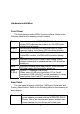
Hardware Installation Front Panel The front panel provides LED’s for device status. Refer to the following table for the meaning of each feature. Power Status WAN Async WLS LAN 1,2,3,4 Power status of the WIRELESS SOHO Router. A steady LED indicates the power is on. No LED lights indicate lack of power. Router status indicates. When router boot or Flash memory writing, then Status LED should be blinking. Wide Area Network status. When connected to the Cable/DSL modem, the WAN LED should be steady on.
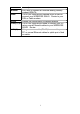
Modem WAN Reset LAN(2,3,4) LAN (1) warranty. Port used to connect an external analog backup modem/ISDN TA. The RJ-45 Ethernet port labeled WAN is used to connect your WIRELESS SOHO Router to your DSL or Cable modem. Resets the configuration to default settings. The RJ-45 Ethernet port used to connect your PC using normal Ethernet cables to your WIRELESS SOHO Router. Using crossover cable (RJ-45) to connect to your PC or normal Ethernet cables to uplink port of hub or switch.
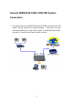
General WIRELESS SOHO ROUTER System Connection 1. The general function of WIRELESS SOHO ROUTER is defined as an “AP + Router”, and the connection is as follow diagram. In this mode, user may connect the WAN port to Cable / DSL modem. The WAN LED will indicate connection. Connect the LAN port to a hub or switch.
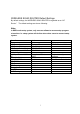
WIRELESS SOHO ROUTER Default Settings By default settings, the WIRELESS SOHO ROUTER is regarded as an “AP Router”. The default settings are shown following. Note: In WEB mode setup system, only one user allows to access setup program at one time i.e. setup system will decline when other users to connect setup system.
Web Management Settings TURN ON POWER SUPPLY Quick power cycle can caused system corruption. When power on, be careful not to shut down in about 5 seconds, because data is writing to the flash. START -UP & LOG IN In order to configure the Wireless SOHO Router, you must use your web browser and manually input 192.168.2.1 into the Address box and press Enter. The Main Page will appear. In order to configure the Wireless SOHO Router, you must input the user-name into the User Name box.
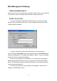
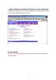
MAKE CORRECT NETWORK SETTINGS OF YOUR COMPUTER To change the configuration, use Internet Explorer (IE) or Netscape Communicator to connect the WEB management 192.168.2.1. SETUP WIZARD Click SETUP WIZARD. Here allow user to configure basic network settings with your ISP provider.
DEVICE INFORMATION The Device Name is the same as the Computer Name that was set in the Setup Wizard. The IP Address is the IP Address assigned to LAN side of your Router. The Private LAN Mac Address the Mac Address assigned to the LAN side of your Router. The Public WAN (Cable/DSL) Mac Address is the Mac Address assigned to the WAN port of the Router. This Mac Address may be used by some cable modem connections. The Firmware Version is the current firmware version used by the Router.
DEVICE STATUS The Device Status screen displays a graphical representation of your current configuration. The left side of the screen shows your connection information in regards to WAN and LAN IP Address information. The right side displays the connection status of each device. This means that there is a connection. This means that there is not a connection. The DHCP Log displays information about each IP Address assigned to a computer using the DHCP server built-in to the Router.
DEVICE IP SETTINGS It’s the LAN network domain settings. The default value is listed as following. (IP Address: 192.168.2.1, IP Subnet Mask: 255.255.255.0) After changing the settings, click NEXT to continue other network settings.
CABLE/ADSL ISP SETTINGS: Here are the cable/ADSL ISP settings i.e. WAN port network settings. By default, the WAN port is set to automatically obtain an IP address from your ISP, if ISP provides DHCP server function. To assign static IP for the WAN port, place a checkmark and enter the settings. After changing the settings, click NEXT to continue other network settings.
ISP ADDITIONAL SETTINGS: To set extra ISP settings, user may set the authentication data here while entering ISP. Here also allow user to set the “idle time”, ”host and domain name” and ”WAN Ethernet MAC address”. After changing the settings, click NEXT to continue other network settings. DSL users: If you are using a PPPoE client to connect to your DSL provider, then place a checkmark on the first box, and enter the user name and password in the appropriate box.
WIRELESS SETTINGS Here allow user to set WIRELESS SOHO ROUTER wireless IP and operation channel. The default value for RF are as followed: ESSID: Wireless, Channel: 6. After changing the setting, click NEXT to save and restart the system.
MODEM SETTINGS An analog external modem can be used as a dialup backup to the DSL/Cable connection. If you would like to use a modem backup, you need to enable the modem settings function. Click on “Modem Settings” on the left hand side and input the ISP account settings. Note: If you change the baud rate settings, please check the initial string. (Please refer to the modem’s manual.
ADVENCED SETTINGS Click ADVENCED SETTINGS. Here allow user to set the advanced settings as main menu list. DHCP SERVER SETTINGS By default, the Wireless Router has DHCP server enabled to assign an IP address ranging from 192.168.2.2 to 192.168.2.100. In addition, the router is capable of reserving up to four sets of IP addresses within the local network for mail, web, or ftp server. After changing the setting, clicks SUBMIT to change the configuration.
VIRTUAL SERVER SETTINGS Here allow user to set several kinds of virtual service of the WIRELESS SOHO ROUTER such as HTTP, SMTP, POP3, FTP, TELNET and IRC service. After changing the setting, clicks SUBMIT to enter inputted data. Specific application support is enabled in Virtual Server Settings under Advanced Settings. Click on the arrow to select the common applications such as FTP, Web server, and mail server.
DMZ The Virtual Server Settings under Advanced Settings also enables one computer to have full access to the Internet without the protection of the firewall. This allows a computer to be exposed to unrestricted two-way communication outside of your network. To enable DMZ, select “All” from menu. Then type the IP address of the selected computer in the box provided. Click the “Submit” button to save your changes. Only one computer can use DMZ at a time.
STATIC SETTINGS In Static Routing, the user has the ability to add a static route to the routing table by simple entering the destination IP, subnet mask, and gateway. Clicking on “Add” and then “Submit” which requires a restart for the IP address to be incorporated into the routing table.
DYNAMIC SETTINGS By default, the Router will not send or receive any routing Internet protocols (RIP) to update the routing table. However, the user can enable the Router to automatically send and receive RIP packets to establish routes for commonly used paths.
22
MODEM STRING SETTINGS Most dial-up modems are compatible with the standard modem strings. However for modems that require special modem strings, the user can enter the information in this screen.
ADMINISTRATION SETTINGS Here allow user to change the password to execute setup system. After changing the setting, clicks SUBMIT .
SYSTEM TOOLS The System Tools section enables you to manage your Wireless SOHO Router and view information related to unit functions. The following functions are described in this chapter. Intruder Detection Log: View detection logs. System Diagnostics: Display current status and connection information. Load Default Settings: Restore settings to factory default. Upgrade Firmware: Upgrade the firmware with a latest version. Reset Device: Reboot the Wireless SOHO Router.
Dest IP (Port): The IP address assigned to the destination of the intruding packet. Event: The type of intrusion. DISPLAY ROUTING TABLE The Display Routing Table screen displays the routing table that the Router is using. A router uses a routing table to keep track of what IP addresses there are and where the router should forward packets when it receives them. Type: The type of routing protocol used. Destination LAN IP Address: Shows the Destination IP Address on the LAN side.
LOAD DEFAULT SETTINGS The Load Default Settings screen enables you to restore the settings that came as default. Click the Start button to begin the process.
UPGRADE FIRMWARE Here allow user to upgrade firmware. After choosing upgrade firmware, click START to load settings. The Upgrade Firmware screen enables you to update the firmware. Updated firmware usually fix problems encountered by users, but may incorporate new features. Begin by clicking the “Browse…” button to browse your computer to select the updated firmware file. Once the firmware file is selected, click the “Start” button to upgrade the firmware.
RESET DEVICE The Reset Device screen enables you to reboot the Wireless SOHO Router. If any changes are made and you want them to take effect, you will need to reset the Wireless SOHO Router to do so. Click the “Start ” button to reset the Wireless SOHO Router. Click the “Cancel” button to cancel.
Troubleshooting Basic Functions My Wireless SOHO Router will not turn on. No LED’s light up. Cause: The power is not connected . Resolution: Connect the power adapter to your WIRELESS SOHO Router and plug it into the power outlet. Note: Only use the power adapter provided with your WIRELESS SOHO Using any other adapter may damage your WIRELESS SOHO Router. Router. LAN Connection Problems I can’t access my WIRELESS SOHO Router. Cause: The unit is not powered on.
I can’t connect to other computers on my LAN. Cause: The IP Addresses of the computers are not set correctly. Network cables are not connected properly. Windows network settings are not set correctly. Resolution: Make sure that each computer has a unique IP Address. If using DHCP through the WIRELESS SOHO Router, make sure that each computer is set to “Obtain an IP Address automatically” and restart the computer.
your service agreement before sharing Internet access. Wireless Troubleshooting I Can’t access the Wireless SOHO Router from a wireless network card Cause: Settings are not the same among each wireless adapter. Out of range. IP Address is not set correctly. Resolution: Make sure that the Mode, SSID, Channel and encryption settings are set the same on each wireless adapter. Make sure that your computer is within range and free from any strong electrical devices that may cause interference.
settings to default configuration or click Cancel to discard any changes. Technical Specifications Standards: IEEE 802.3 10BASE-T Ethernet IEEE 802.3u 100BASE-TX Fast Ethernet ANSI/IEEE 802.3 NWay auto-negotiation Protocols Supported: TCP IP NAT UDP PPPoE DHCP (Client and Server) Management: Web-Based Ports: LAN: NWay 10BASE-T/100BASE-TX Fast Ethernet WAN: 10BASE-T RS-232 (DB-9) Serial Wireless SOHO Router Specifications General Wireless Specifications: IEEE 802.
Japan : 14 (1-14) Access Point Frequency Range: 5 Mbps Access Point Data Rate: 11 Mbps 5.5 Mbps 2 Mbps 1 Mbps Data encryption: 40 bit WEP and ESSID for Security LED: Power : Indicate power is ON Status : Indicate Firmware loading under proceeding WAN : LAN : Indicate WAN port connection Indicate LAN port TX/RX operation WLAN: Indicate Wireless been connected and operation Power Specifications : DC power supply Input: DC 100-240 50-60 Hz 1A Output: 5V DC 1A converter incl.
Federal Communication Commission Interference Statement This equipment has been tested and found to comply with the limits for a Class B digital device, pursuant to Part 15 of the FCC Rules. These limits are designed to provide reasonable protection against harmful interference in a residential installation. This equipment generates, uses and can radiate radio frequency energy and, if not installed and used in accordance with the instructions, may cause harmful interference to radio communications.
R&TTE Compliance Statement This equipment complies with all the requirements of the DIRECTIVE 1999/5/EC OF THE EUROPEAN PARLIAMENT AND THE COUNCIL of 9 March 1999 on radio equipment and telecommunication terminal Equipment and the mutual recognition of their conformity (R&TTE). The R&TTE Directive repeals and replaces in the directive 98/13/EEC (Telecommunications Terminal Equipment and Satellite Earth Station Equipment) As of April 8, 2000 .
Copyright statement No part of this publication may be reproduced, stored in a retrieval system, or transmitted in any form or by any means, whether electronic, mechanical, photocopying, recording, or otherwise without the prior writing of the publisher.