Gemtek Technology Co., Ltd. WRTM-106B Wireless 11b Router User's Manual Aug. 8, 2003 (Draft 1.
Contents 1. INTRODUCTION ........................................................................................... 3 1.1 Wireless Router Features ........................................................................................... 3 1.2 Package Contents ........................................................................................................ 5 1.3 Physical Details............................................................................................................ 6 2.
7.5 Logs............................................................................................................................. 77 7.6 MAC Address ............................................................................................................ 79 7.7 Routing ....................................................................................................................... 80 APPENDIX A TROUBLESHOOTING ......................................... 85 A1. Overview...........................
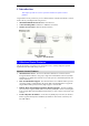
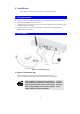
1. Introduction This Chapter provides an overview of the Wireless Router's features and capabilities. Congratulations on the purchase of your new Wireless Router. The Wireless Router is a multifunction device providing the following services: • • • Shared Broadband Internet Access for all LAN users. 4-Port Switching Hub for 10BaseT or 100BaseT connections. Wireless Access Point for 802.11b Wireless Stations. Figure 1: Wireless Router 1.
Advanced Internet Functions • Communication Applications. Support for Internet communication applications, such as interactive Games, Telephony, and Conferencing applications, which are often difficult to use when behind a Firewall, is included. • Special Internet Applications. Applications which use non-standard connections or port numbers are normally blocked by the Firewall. The ability to define and allow such applications is provided, to enable such applications to be used normally.
Security Features • Password - protected Configuration. Optional password protection is provided to prevent unauthorized users from modifying the configuration data and settings. • Wireless LAN Security. WEP (Wired Equivalent Privacy) is supported, as well as Wireless access control to prevent unknown wireless stations from accessing your LAN. • NAT Protection.
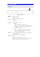
1.3 Physical Details Front Panel Figure 2: Front Panel Status (Red) LED On - Error condition. Off - Normal operation. Blinking - This LED blinks during start up. Power LED On - Power on. Off - No power. LAN LEDs For each port, there are 2 LEDs • Link/Act • • WAN LED On - Corresponding LAN (hub) port is active. • Off - No active connection on the corresponding LAN (hub) port. • Flashing - Data is being transmitted or received via the corresponding LAN (hub) port.
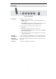
Rear Panel Figure 3: Rear Panel Reset Button This button has two (2) functions: • Reboot. When pressed and released, the Wireless Router will reboot (restart). • Clear All Data. This button can also be used to clear ALL data and restore ALL settings to the factory default values. To Clear All Data and restore the factory default values: 1. Power Off. 2. Hold the Reset Button down while you Power On. 3. Keep holding the Reset Button for a few seconds, until the RED LED has flashed TWICE. 4.
2. Installation This Chapter covers the physical installation of the Wireless Router. 2.1 Requirements • Network cables. Use standard 10/100BaseT network (UTP) cables with RJ45 connectors. • TCP/IP protocol must be installed on all PCs. • For Internet Access, an Internet Access account with an ISP, and either of a DSL or Cable modem (for WAN port usage) • To use the Wireless Access Point, all Wireless devices must be compliant with the IEEE802.11b specifications. 2.
Installation 2. Connect LAN Cables Use standard LAN cables to connect PCs to the Switching Hub ports on the Wireless Router. Both 10BaseT and 100BaseT connections can be used simultaneously. 3. Connect WAN Cable Connect the DSL or Cable modem to the WAN port on the Wireless Router. Use the cable supplied with your DSL/Cable modem. If no cable was supplied, use a standard cable. 4. Power Up • Power on the Cable or DSL modem. • Connect the supplied power adapter to the Wireless Router and power up.
3. Setup This Chapter provides Setup details of the Wireless Router. 3.1 Overview This chapter describes the setup procedure for: • Internet Access • LAN configuration • Wireless setup • Assigning a Password to protect the configuration data. PCs on your local LAN may also require configuration. For details, see Chapter 4 - PC Configuration. Other configuration may also be required, depending on which features and functions of the Wireless Router you wish to use.
Setup 3.2 Configuration Program The Wireless Router contains an HTTP server. This enables you to connect to it, and configure it, using your Web Browser. Your Browser must support JavaScript. The configuration program has been tested on the following browsers: • Netscape V4.08 or later • Internet Explorer V4 or later Preparation Before attempting to configure the Wireless Router, please ensure that: • Your PC can establish a physical connection to the Wireless Router.
If you can't connect If the Wireless Router does not respond, check the following: • The Wireless Router is properly installed, LAN connection is OK, and it is powered ON. You can test the connection by using the "Ping" command: • Open the MS-DOS window or command prompt window. • Enter the command: ping 192.168.2.1 If no response is received, either the connection is not working, or your PC's IP address is not compatible with the Wireless Router's IP Address. (See next item.
Setup 3.3 Setup Wizard The first time you connect to the Wireless Router, the Setup Wizard will run automatically. (The Setup Wizard will also run if the Wireless Router's default settings are restored.) 1. Step through the Wizard until finished. • 2. 3. You need to know the type of Internet connection service used by your ISP. Check the data supplied by your ISP. • The common connection types are explained in the tables below.
PPTP Mainly used in Europe. • PPTP Server IP Address. You connect to the ISP only when required. The IP address is usually allocated automatically, but may be Static (Fixed). • User name and password. • IP Address allocated to you, if Static (Fixed). Other Modems (e.g. Broadband Wireless) Type Details ISP Data required Dynamic IP Address Your IP Address is allocated automatically, when you connect to you ISP. None. Static (Fixed) IP Address Your ISP allocates a permanent IP Address to you.
Setup Home Screen After finishing the Setup Wizard, you will see the Home screen. When you connect in future, you will see this screen when you connect. An example screen is shown below. Figure 5: Home Screen Navigation & Data Input • Use the menu bar on the top of the screen, and the "Back" button on your Browser, for navigation. • Changing to another screen without clicking "Save" does NOT save any changes you may have made. You must "Save" before changing screens or your data will be ignored.
3.4 LAN Screen Use the LAN link on the main menu to reach the LAN screen. The example screen is shown below. 2 Figure 6: LAN Screen Data - LAN Screen TCP/IP IP Address IP address for the Wireless Router, as seen from the local LAN. Use the default value unless the address is already in use or your LAN is using a different IP address range. In the latter case, enter an unused IP Address from within the range used by your LAN. Subnet Mask The default value 255.255.255.
Setup DHCP What DHCP Does A DHCP (Dynamic Host Configuration Protocol) Server allocates a valid IP address to a DHCP Client (PC or device) upon request. • The client request is made when the client device starts up (boots). • The DHCP Server provides the Gateway and DNS addresses to the client, as well as allocating an IP Address. • The Wireless Router can act as a DHCP server. • Windows 95/98/ME and other non-Server versions of Windows will act as a DHCP client.
3.5 Wireless Screen The Wireless Access Point settings must match the other Wireless stations. To change the Wireless Router's default settings for the Wireless Access Point feature, use the Wireless link on the main menu to reach the Wireless screen. An example screen is shown below. Figure 7: Wireless Screen Data - Wireless Screen Identification Regulatory Domain It is illegal to use this device in any location outside of the regulatory domain.
Setup WEP data encryption • WEP (Wired Equivalent Privacy) status will display "Enabled" or "Disabled", depending on whether WEP is being used. If used, data is Encrypted before being transmitted, making communication more secure. • Click the "Configure WEP" button to access the WEP sub-screen, and view or change the WEP settings. • All Wireless Stations - All wireless stations can use the access point to access your LAN.
Figure 8: WEP Screen Data - WEP Screen WEP Data Encryption WEP Data Encryption Select the option to match other Wireless Stations: • Disabled - data is NOT encrypted before being transmitted. • 64 Bit - data is encrypted, using the default key, before being transmitted. You must enter at least the default key. For 64 Bit Encryption, the key size is 5 chars (ASCII) or 10 chars in HEX (0~9 and A~F). • 128 Bit - data is encrypted, using the default key, before being transmitted.
Setup ted data is ALWAYS encrypted using the Default Key; the other Keys are for decryption only. • Passphrase Key Value - Enter the key value you wish to use. Other stations must have the same key. If desired, you can generate a key from a phrase, instead of entering the key value directly. Enter the desired phrase, and click the "Generate Keys" button.
3.6 Password Screen The password screen allows you to assign a password to the Wireless Router. Figure 9: Password Screen Once you have assigned a password to the Wireless Router (on the Password screen above) you will be prompted for the password when you connect, as shown below. (If no password has been set, this dialog will not appear.) Figure 10: Password Dialog • Default User Name: admin Default Password: admin • Enter the password for the Wireless Router, as set on the Password screen above.
4.PC Configuration This Chapter details the PC Configuration required on the local ("Internal") LAN. 4.1 Overview For each PC, the following may need to be configured: • TCP/IP network settings • Internet Access configuration • Wireless configuration 4.2 Windows Clients This section describes how to configure Windows clients for Internet access via the Wireless Router. The first step is to check the PC's TCP/IP settings.
Wireless Router User Guide Checking TCP/IP Settings - Windows 9x/ME: 1. Select Control Panel - Network. You should see a screen like the following: Figure 11: Network Configuration 2. 3. Select the TCP/IP protocol for your network card. Click on the Properties button. You should then see a screen like the following. Figure 12: IP Address (Win 95) Ensure your TCP/IP settings are correct, as follows: Using DHCP To use DHCP, select the radio button Obtain an IP Address automatically.
PC Configuration • On the Gateway tab, enter the Wireless Router's IP address in the New Gateway field and click Add, as shown below. Your LAN administrator can advise you of the IP Address they assigned to the Wireless Router. Figure 13: Gateway Tab (Win 95/98) • On the DNS Configuration tab, ensure Enable DNS is selected. If the DNS Server Search Order list is empty, enter the DNS address provided by your ISP in the fields beside the Add button, then click Add.
Wireless Router User Guide Checking TCP/IP Settings - Windows NT4.0 1. Select Control Panel - Network, and, on the Protocols tab, select the TCP/IP protocol, as shown below. Figure 15: Windows NT4.0 - TCP/IP 2. Click the Properties button to see a screen like the one below.
PC Configuration Figure 16: Windows NT4.0 - IP Address 3. 4. Select the network card for your LAN. Select the appropriate radio button - Obtain an IP address from a DHCP Server or Specify an IP Address, as explained below. Obtain an IP address from a DHCP Server This is the default Windows setting. Using this is recommended. By default, the Wireless Router will act as a DHCP Server. Restart your PC to ensure it obtains an IP Address from the Wireless Router.
Wireless Router User Guide Figure 17 - Windows NT4.0 - Add Gateway 2. The DNS should be set to the address provided by your ISP, as follows: • Click the DNS tab. • On the DNS screen, shown below, click the Add button (under DNS Service Search Order), and enter the DNS provided by your ISP.
PC Configuration Figure 18: Windows NT4.
Wireless Router User Guide Checking TCP/IP Settings - Windows 2000: 1. 2. Select Control Panel - Network and Dial-up Connection. Right - click the Local Area Connection icon and select Properties. You should see a screen like the following: Figure 19: Network Configuration (Win 2000) 3. 4. Select the TCP/IP protocol for your network card. Click on the Properties button. You should then see a screen like the following.
PC Configuration Figure 20: TCP/IP Properties (Win 2000) 5. Ensure your TCP/IP settings are correct, as described below. Using DHCP To use DHCP, select the radio button Obtain an IP Address automatically. This is the default Windows setting. Using this is recommended. By default, the Wireless Router will act as a DHCP Server. Restart your PC to ensure it obtains an IP Address from the Wireless Router.
Wireless Router User Guide Checking TCP/IP Settings - Windows XP 1. 2. Select Control Panel - Network Connection. Right click the Local Area Connection and choose Properties. You should see a screen like the following: Figure 21: Network Configuration (Windows XP) 3. 4. Select the TCP/IP protocol for your network card. Click on the Properties button. You should then see a screen like the following.
PC Configuration Figure 22: TCP/IP Properties (Windows XP) 5. Ensure your TCP/IP settings are correct. Using DHCP To use DHCP, select the radio button Obtain an IP Address automatically. This is the default Windows setting. Using this is recommended. By default, the Wireless Router will act as a DHCP Server. Restart your PC to ensure it obtains an IP Address from the Wireless Router.
Wireless Router User Guide Internet Access To configure your PCs to use the Wireless Router for Internet access: • Ensure that the DSL modem, Cable modem, or other permanent connection is functional. • Use the following procedure to configure your Browser to access the Internet via the LAN, rather than by a Dial-up connection. For Windows 9x/ME/2000 1. 2. 3. 4. 5. 6. 7. Select Start Menu - Settings - Control Panel - Internet Options. Select the Connection tab, and click the Setup button.
PC Configuration 4.3 Macintosh Clients From your Macintosh, you can access the Internet via the Wireless Router. The procedure is as follows. 1. Open the TCP/IP Control Panel. 2. Select Ethernet from the Connect via pop-up menu. 3. Select Using DHCP Server from the Configure pop-up menu. The DHCP Client ID field can be left blank. 4. Close the TCP/IP panel, saving your settings.
Wireless Router User Guide 4.6 Wireless Station Configuration This section applies to all Wireless stations wishing to use the Wireless Router's Access Point, regardless of the operating system which is used on the client. To use the Wireless Access Point in the Wireless Router, each Wireless Station must have compatible settings, as follows: Mode The mode must be set to Infrastructure. SSID (ESSID) This must match the value used on the Wireless Router.
5. Operation and Status This Chapter details the operation of the Wireless Router and the status screens. 5.1 Operation Once both the Wireless Router and the PCs are configured, operation is automatic. However, there are some situations where additional Internet configuration may be required: • If using Internet-based Communication Applications, it may be necessary to specify which PC receives an incoming connection. Refer to Chapter 6 - Advanced Features for further details.
Wireless Router User Guide Data - Status Screen Internet Connection Method This indicates the current connection method, as set in the Setup Wizard. Broadband Modem This shows the connection status of the modem. Internet Connection Current connection status: • Active • Idle • Unknown • Failed If there is an error, you can click the "Connection Details" button to find out more information. Internet IP Address This IP Address is allocated by the ISP (Internet Service Provider).
Operation and Status 5.3 Connection Status - PPPoE If using PPPoE (PPP over Ethernet), a screen like the following example will be displayed when the "Connection Details" button is clicked. Figure 24: PPPoE Status Screen Data - PPPoE Connection Physical Address The hardware address of this device, as seen by remote devices on the Internet. (This is different to the hardware address seen by devices on the local LAN.) IP Address The IP Address of this device, as seen by Internet users.
Wireless Router User Guide lished. • If the connection does not exist, the "Connect" button can be used to establish a connection. • If the connection currently exists, the "Disconnect" button can be used to break the connection. • The Connection Log shows status messages relating to the existing connection. • The most common messages are listed in the table below. • The "Clear Log" button will restart the Log, while the Refresh button will update the messages shown on screen.
Operation and Status Error: Connection to Server lost The existing connection has been lost. This could be caused by a power failure, a link failure, or Server failure. Error: Invalid or unknown packet type The data received from the ISP's Server could not be processed. This could be caused by data corruption (from a bad link), or the Server using a protocol which is not supported by this device.
Wireless Router User Guide 5.4 Connection Status - PPTP If using PPTP (Peer-to-Peer Tunneling Protocol), a screen like the following example will be displayed when the "Connection Details" button is clicked. Figure 25: PPTP Status Screen Data - PPTP Connection Physical Address The hardware address of this device, as seen by remote devices on the Internet. (This is different to the hardware address seen by devices on the local LAN.) IP Address The IP Address of this device, as seen by Internet users.
Operation and Status used to break the connection. Connection Log Connection Log • The Connection Log shows status messages relating to the existing connection. • The "Clear Log" button will restart the Log, while the Refresh button will update the messages shown on screen. Buttons Connect If not connected, establish a connection to your ISP. Disconnect If connected to your ISP, hang up the connection. Clear Log Delete all data currently in the Log. This will make it easier to read new messages.
Wireless Router User Guide Data - Big Pond Connection Physical Address The hardware address of this device, as seen by remote devices. (This is different to the hardware address seen by devices on the local LAN.) IP Address The IP Address of this device, as seen by Internet users. This address is allocated by your ISP (Internet Service Provider). Connection Status This indicates whether or not the connection is currently established.
Operation and Status Figure 27: Connection Details - RAS Data - RAS Internet RAS Plan The RAS Plan which is currently used. Physical Address The hardware address of this device, as seen by remote devices on the Internet. (This is different to the hardware address seen by devices on the local LAN.) IP Address The IP Address of this device, as seen by Internet users. This address is allocated by your ISP (Internet Service Provider). Network Mask The Network Mask associated with the IP Address above.
Wireless Router User Guide Button will display EITHER "Release" OR "Renew" Refresh Fixed (Static) IP address, this button has no effect. • If the ISP's DHCP Server has NOT allocated an IP Address for the Wireless Router, this button will say "Renew". Clicking the "Renew" button will attempt to re-establish the connection and obtain an IP Address from the ISP's DHCP Server. • If an IP Address has been allocated to the Wireless Router (by the ISP's DHCP Server), this button will say "Release".
Operation and Status 5.7 Connection Details - Fixed/Dynamic IP Address If your access method is "Direct" (no login), a screen like the following example will be displayed when the "Connection Details" button is clicked. Figure 28: Connection Details - Fixed/Dynamic IP Address Data - Fixed/Dynamic IP address Internet Physical Address The hardware address of this device, as seen by remote devices on the Internet. (This is different to the hardware address seen by devices on the local LAN.
Wireless Router User Guide to manually renew the lease immediately. Buttons Release/Renew Button will display EITHER "Release" OR "Renew" Refresh This button is only useful if the IP address shown above is allocated automatically on connection. (Dynamic IP address). If you have a Fixed (Static) IP address, this button has no effect. • If the ISP's DHCP Server has NOT allocated an IP Address for the Wireless Router, this button will say "Renew".
6. Advanced Features This Chapter explains when and how to use the Wireless Router's "Advanced" Features. 6.1 Overview The following advanced features are provided. • Advanced Internet • Communication Applications • Special Applications • DMZ • URL filter • Access Control • Remote Management • Virtual Servers • Dynamic DNS • Firmware Upgrade 6.2 Advanced Menu Screen This screen provides access to the advanced features. An example screen is shown below.
Wireless Router User Guide 6.3 Advanced Internet Screen This screen allows configuration of all advanced features relating to Internet access. • Communication Applications • Special Applications • DMZ • URL filter An example screen is shown below. Figure 30: Internet Screen Communication Applications Most applications are supported transparently by the Wireless Router. But sometimes it is not clear which PC should receive an incoming connection.
Advanced Features Send incoming calls to This lists the PCs on your LAN. • If necessary, you can add PCs manually, using the "PC Database" option on the advanced menu. • For each application listed above, you can choose a destination PC. • There is no need to "Save" after each change; you can set the destination PC for each application, then click "Save".
Wireless Router User Guide Data - Special Applications Screen Checkbox Use this to Enable or Disable this Special Application as required. Name Enter a descriptive name to identify this Special Application. Incoming Ports Outgoing Ports • Type - Select the protocol (TCP or UDP) used when you receive data from the special application or service. (Note: Some applications use different protocols for outgoing and incoming data).
Advanced Features URL Filter The URL Filter allows you to block access to undesirable Web site • To use this feature, you must define "filter strings". If the "filter string" appears in a requested URL, the request is blocked. • Enabling the URL Filter also affects the Internet Access Log. If Enabled, the "Destination" field in the log will display the URL. Otherwise, it will display the IP Address. • The URL Filter can be Enabled or Disabled on the Advanced Internet screen.
Wireless Router User Guide Buttons Delete/Delete All Use these buttons to delete the selected entry or all entries, as required. Multiple entries can be selected by holding down the CTRL key while selecting.(On the Macintosh, hold the SHIFT key while selecting.) Add Use this to add the current Filter String to the site list. 6.4 Access Control This feature is accessed by the Access Control link on the Advanced menu.
Advanced Features Figure 33: Access Control Screen Data - Access Control Screen Group Group Select the desired Group. The screen will update to display the settings for the selected Group. Groups are named "Default", "Group 1", "Group 2", "Group 3" and "Group 4", and cannot be renamed. "Members" Button Click this button to add or remove members from the current Group. • If the current group is "Default", then members can not be added or deleted.
Wireless Router User Guide Internet Access Restrictions Select the desired options for the current group: • None - Nothing is blocked. Use this to create the least restrictive group. • Block all Internet access - All traffic via the WAN port is blocked. Use this to create the most restrictive group. • Block selected Services - You can select which Services are to block. Use this to gain fine control over the Internet access for a group.
Advanced Features Figure 34: Group Members Use this screen to add or remove members (PCs) from the current group. • The "Del >>" button will remove the selected PC (in the Members list) from the current group. • The "<< Add" button will add the selected PC (in the Other PCs list) to the current group. PCs not assigned to any group will be in the "Default" group. PCs deleted from any other Group will be added to the "Default" group.
Wireless Router User Guide Default Schedule Screen This screen is displayed when the Define Schedule button on the Access Control screen is clicked. • This schedule can be (optionally) applied to any Access Control Group. • Blocking will be performed during the scheduled time (between the "Start" and "Finish" times.) • Two (2) separate sessions or periods can be defined. • Times must be entered using a 24 hr clock. • If the time for a particular day is blank, no action will be performed.
Advanced Features Services Screen This screen is displayed when the Edit Service List button on the Access Control screen is clicked. Figure 36: Access Control - Services Data - Services Screen Available Services Available Services This lists all the available services. "Delete" button Use this to delete any Service you have added. Pre-defined Services can not be deleted. Add New Service Name Enter a descriptive name to identify this service.
Wireless Router User Guide Finish Port For TCP and UDP Services, enter the end of the range of port numbers used by the service. If the service uses a single port number, enter it in both the "Start" and "Finish" fields. ICMP Type For ICMP Services, enter the type number of the required service. Buttons Delete Delete the selected service from the list. Save Add a new entry to the Service list, using the data shown in the "Add New Service" area on screen.
Advanced Features 6.5 Remote Management This feature allows you to manage the Wireless Router via the Internet. Figure 37: Remote Management Screen Data - Remote Management Screen Remote Management Enable Remote Management Enable to allow management via the Internet. If Disabled, this device will ignore management connection attempts from the Internet. Port Number Enter a port number between 1024 and 65535 (8080 is recommended). This port number must be specified when you connect (see below).
Wireless Router User Guide 6.6 Virtual Servers This feature allows you to make Servers on your LAN accessible to Internet users. Normally, Internet users would not be able to access a server on your LAN because: • Your Server does not have a valid external IP Address. • Attempts to connect to devices on your LAN are blocked by the firewall in this device. The "Virtual Server" feature solves these problems and allows Internet users to connect to your servers, as illustrated below. 192.168.0.
Advanced Features Virtual Servers Screen The Virtual Servers screen is reached by the Virtual Servers link on the Advanced screen. An example screen is shown below. Figure 39: Virtual Servers Screen This screen lists a number of pre-defined Servers, and allows you to define your own Servers. Details of the selected Server are shown in the "Properties" area. Data - Virtual Servers Screen Servers Servers This lists a number of pre-defined Servers, plus any Servers you have defined.
Wireless Router User Guide Internal Port No. Enter the port number which the Server software is configured to use. External Port No. The port number used by Internet users when connecting to the Server. This is normally the same as the Internal Port Number. If it is different, this device will perform a "mapping" or "translation" function, allowing the server to use one port address, while clients use a different port address.
Advanced Features From the Internet, ALL Virtual Servers have the IP Address allocated by your ISP. Connecting to the Virtual Servers Once configured, anyone on the Internet can connect to your Virtual Servers. They must use the Internet IP Address (the IP Address allocated to you by your ISP). e.g. http://203.70.212.52 ftp://203.70.212.52 It is more convenient if you are using a Fixed IP Address from your ISP, rather than Dynamic.
Wireless Router User Guide Dynamic DNS Screen Select Advanced on the main menu, then Dynamic DNS, to see a screen like the following: Figure 40: DDNS Screen Data - Dynamic DNS Screen DDNS Service DDNS Service • You must sign up first to create a new account before using the service. The service is free. • Click this link to connect to the www.dyndns.org Web site. • Your initial password will be E-mailed to you; you can change this later if you wish.
Advanced Features was not allocated to you. You need to connect to www.dyndns.org and correct this problem. 6.8 Upgrade Firmware The firmware (software) in the Wireless Router can be upgraded using your Web Browser. You must first download the upgrade file, and then select Upgrade on the Advanced menu. You will see a screen like the following. Figure 41: Upgrade Firmware Screen To perform the Firmware Upgrade: 1. 2. 3. Click the "Browse" button and navigate to the location of the upgrade file.
7. Advanced Configuration This Chapter explains the settings available via the Advanced configuration section of the "Advanced" menu. 7.1 Overview Normally, it is not necessary to use these screens, or change any settings. These screens and settings are provided to deal with non-standard situations, or to provide additional options for advanced users. The settings available are: PC Database This is the list of PCs shown when you select the "DMZ PC" or a "Virtual Server".
Advanced Configuration 7.2 PC Database The PC Database is used whenever you need to select a PC (e.g. for the "DMZ" PC). It eliminates the need to enter IP addresses. Also, you do not need to use fixed IP addresses on your LAN. PC Database Screen An example PC Database screen is shown below. Figure 42: PC Database • PCs which are "DHCP Clients" are automatically added to the database, and updated as required.
Wireless Router User Guide Data - PC Database Screen Known PCs This lists all current entries. Data displayed is name (IP Address) type. The "type" indicates whether the PC is connected to the LAN. Name If adding a new PC to the list, enter its name here. It is best if this matches the PC's "hostname". IP Address Enter the IP Address of the PC. The PC will be sent a "ping" to determine its hardware address. If the PC is not available (not connected, or not powered On) you will not be able to add it.
Advanced Configuration PC Database (Admin) This screen is displayed if the "Advanced Administration" button on the PC Database is clicked. It provides more control than the standard PC Database screen. Figure 43: PC Database (Admin) Data - PC Database ( Admin) Screen Known PCs This lists all current entries. Data displayed is name (IP Address) type. The "type" indicates whether the PC is connected to the LAN. PC Properties Name If adding a new PC to the list, enter its name here.
Wireless Router User Guide IP Address MAC Address Select the appropriate option: • Automatic - The PC is set to be a DHCP client (Windows: "Obtain an IP address automatically"). The Wireless Router will allocate an IP address to this PC when requested to do so. The IP address could change, but normally won't. • DCHP Client - Reserved IP Address - Select this if the PC is set to be a DCHP client, and you wish to guarantee that the Wireless Router will always allocate the same IP Address to this PC.
Advanced Configuration 7.3 Options This screen allows advanced users to enter or change a number of settings. For normal operation, there is no need to use this screen or change any settings. An example Options screen is shown below. Figure 44: Options Screen Data - Options Screen Backup DNS IP Address Enter the IP Address of the DNS (Domain Name Servers) here. These DNS will be used only if the primary DNS is unavailable.
Wireless Router User Guide Allow Configuration... Allow Internet access to be disabled • If checked, then UPnP users can change the configuration. • If Disabled, UPnP users can only view the configuration. But currently, this restriction only applies to users running Windows XP, who access the Properties via UPnP. (e.g. Right - click the Wireless Router in My Network Places, and select Properties) • If checked, then UPnP users can disable Internet access via this device.
Advanced Configuration 7.4 Security This screen allows you to set Firewall and other security-related options. Figure 45: Security Screen Data - Security Screen Firewall Enable DoS Firewall If enabled, DoS (Denial of Service) attacks will be detected and blocked. The default is enabled. It is strongly recommended that this setting be left enabled.
Wireless Router User Guide Options Respond to ICMP Allow IPsec Allow PPTP Allow L2TP The ICMP protocol is used by the "ping" and "traceroute" programs, and by network monitoring and diagnostic programs. • If checked, the Wireless Router will repond to ICMP packets received from the Internet. • If not checked, ICMP packets from the Internet will be ignored. Disabling this option provides a slight increase in security.
Advanced Configuration 7.5 Logs The Logs record various types of activity on the Wireless Router. This data is useful for troubleshooting, but enabling all logs will generate a large amount of data and adversely affect performance. Since only a limited amount of log data can be stored in the Wireless Router, log data can also be E-mailed to your PC. Figure 46: Logs Screen Data - Logs Screen Enable Logs Outgoing Connections If selected, Outgoing Internet connections are logged.
Wireless Router User Guide Timezone Select the correct Timezone for your location. This is required for the date/time shown on the logs to be correct. E-Mail Reports Send E-mail alert If enabled, an E-mail will be sent immediately if a DoS (Denial of Service) attack is detected. If enabled, the E-mail address information must be provided. E-mail Logs You can choose to have the logs E-mailed to you, by enabling either or both checkboxes. If enabled, the Log will sent to the specified E-mail address.
Advanced Configuration 7.6 MAC Address The MAC (hardware) address is a low-level network identifier. It may be called "MAC Address", "Hardware Address", or "Physical Address". On a PC, this address is associated with the Network card or adapter. The address on the MAC Address screen is the address on the Internet (WAN port) interface, and has no effect on the LAN interface.
Wireless Router User Guide If the MAC address is changed, the Wireless Router must restart. 7.7 Routing Overview • If you don't have other Routers or Gateways on your LAN, you can ignore the "Routing" page completely. • If the Wireless Router is only acting as a Gateway for the local LAN segment, ignore the "Routing" page even if your LAN has other Routers. • If your LAN has a standard Router (e.g.
Advanced Configuration Figure 48: Routing Screen Data - Routing Screen RIP Enable RIP Check this to enable the RIP (Routing Information Protocol) feature of the Wireless Router. The Wireless Router supports RIP 1 only. Static Routing Static Routing Table Entries This list shows all entries in the Routing Table. • The "Properties" area shows details of the selected item in the list. • Change any the properties as required, then click the "Update" button to save the changes to the selected entry.
Wireless Router User Guide Properties • Destination Network - The network address of the remote LAN segment. For standard class "C" LANs, the network address is the first 3 fields of the Destination IP Address. The 4th (last) field can be left at 0. • Network Mask - The Network Mask for the remote LAN segment. For class "C" networks, the default mask is 255.255.255.
Advanced Configuration Other Routers on the Local LAN Other routers on the local LAN must use the Wireless Router's Local Router as the Default Route. The entries will be the same as the Wireless Router's local router, with the exception of the Gateway IP Address. • For a router with a direct connection to the Wireless Router's local Router, the Gateway IP Address is the address of the Wireless Router's local router.
Wireless Router User Guide For Router B's Default Route Destination IP Address 0.0.0.0 Network Mask 0.0.0.0 Gateway IP Address 192.168.1.
Appendix A Troubleshooting This Appendix covers the most likely problems and their solutions. A1. Overview This chapter covers some common problems that may be encountered while using the Wireless Router and some possible solutions to them. If you follow the suggested steps and the Wireless Router still does not function properly, contact your dealer for further advice. A2. General Problems Problem 1: Can't connect to the Wireless Router to configure it.
Wireless Router User Guide If this does solve the problem you can use the DMZ function. This should work with almost every application, but: • It is a security risk, since the firewall is disabled. • Only one (1) PC can use this feature. A4. Wireless Access Problem 1: My PC can't locate the Wireless Access Point. Solution 1: Check the following. • Your PC is set to Infrastructure Mode.
Appendix B About Wireless LANs This Appendix provides some background information about using Wireless LANs (WLANs). B1. Modes Wireless LANs can work in either of two (2) modes: • Ad-hoc • Infrastructure Ad-hoc Mode Ad-hoc mode does not require an Access Point or a wired (Ethernet) LAN. Wireless Stations (e.g. notebook PCs with wireless cards) communicate directly with each other. Infrastructure Mode In Infrastructure Mode, one or more Access Points are used to connect Wireless Stations (e.g.
Wireless Router User Guide • Access Points use a fixed Channel. You can select the Channel used. This allows you to choose a Channel which provides the least interference and best performance. In the USA and Canada, 11 channels are available. If using multiple Access Points, it is better if adjacent Access Points use different Channels to reduce interference. • In "Infrastructure" mode, Wireless Stations normally scan all Channels, looking for an Access Point.
Appendix C Specifications C1. Multi-Function Wireless Router Model Wireless Router Dimensions 189mm(W) * 122mm(D) * 27mm(H) Operating Temperature 0° C to 40° C Storage Temperature -10° C to 70° C Network Protocol: TCP/IP Network Interface: 5 Ethernet: 4 * 10/100BaseT (RJ45) LAN connection 1 * 10/100BaseT (RJ45) for WAN Wireless interface Wireless Access Point via built-in wireless module. LEDs 12 Power Adapter 12 V DC External Relative humidity 10% to 90% C2.
Wireless Router User Guide C3. FCC Statement This equipment has been tested and found to comply with the limits for a Class B digital device, pursuant to Part 15 of the FCC Rules. These limits are designed to provide reasonable protection against harmful interference in a residential installation. This equipment generates uses and can radiate radio frequency energy and, if not installed and used in accordance with the instructions, may cause harmful interference to radio communications.