BW1330 High Performance Hotspot Access Point User Guide Version 1.0 September, 2006 www.browan.com Copyright©2006 BROWAN Communications, Inc.
Copyright © 2002-2006 Browan Communications. This user’s guide and the software described in it are copyrighted with all rights reserved. No part of this publication may be reproduced, transmitted, transcribed, stored in a retrieval system, or translated into any language in any form by any means without the written permission of Browan Communications. Notice Browan Communications reserves the right to change specifications without prior notice.
FCC Warning CE Mark Warning This equipment has been tested and found to comply with the limits for a Class B digital device, pursuant to Part 15 of the FCC Rules. These limits are designed to provide reasonable protection against harmful interference in a residential installation. This is a Class A product. In a domestic environment this product may cause radio interference in which case the user may be required to take adequate measures.
User’s Guide Version 1.0 Contents Copyright ............................................................................................................................................. 1 Notice .................................................................................................................................................. 1 Trademarks .........................................................................................................................................
User’s Guide Version 1.0 CHAPTER 5 – CUSTOMIZED USER PAGE (HTML) .......................................................................... 39 Determine Your Access Policy.......................................................................................................... 39 Configure Authentication-Free Access Policy ................................................................................... 39 FAQ ..............................................................................................
User’s Guide Version 1.0 User Interface.................................................................................................................................... 87 User Interface | Configuration | Pages...........................................................................................87 User Interface | Configuration | Upload .........................................................................................88 User Interface | Configuration | Headers ..............................
User’s Guide Version 1.0 B) Regulatory Domain/Channels.....................................................................................................130 C) CLI Commands and Parameters................................................................................................131 Network Commands ....................................................................................................................131 User Commands ......................................................................
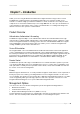
User’s Guide Version 1.0 About this Guide Purpose This document provides information and procedures on hardware installation, setup, configuration, and management of the Browan Communications high performance hotspot access point model BW1330. The BW1330 is a highly integrated Access Controller with built-in AAA systems for public access hotspot. We will call it AC later in the manual.
User’s Guide Version 1.0 Chapter 1 – Introduction Thank you for choosing the Browan Communications High Performance Hopspot Access Point. The BW1330 is a high performance and highly integrated Access Controller for public access networks. It combines a high-speed wireless LAN Access Point, an IP Router, one LAN port and a complete Access Controller for Wi-Fi Hotspot.
User’s Guide Version 1.0 The BW1330 Features WLAN 802.11b+g compliant, 1-54Mbps with auto-fallback Wi-Fi compliant Support Multiple BSSID up to 16 "Virtual AP" Concurrent 802.11b and 802.11g access WDS support (concurrent bridge and AP mode) WPA/WPA2 (Wi-Fi Protected Access) support R-TNC connectors for external antennas RF output power High receiver sensivity (up to -91 dBm@1Mbps, 8%PER) AAA Multiple authentication methods: UAM, 802.
User’s Guide Version 1.0 Chapter 2 – Installation This chapter provides installation instructions for the hardware and software components of the Access Controller BW1330.
User’s Guide Version 1.0 Hardware Introduction General Overview Figure 1 –BW1330 Access Controller General View The front panel of the Access Controller contains: A series of indicator lights (LEDs) that help describe the state of various networking and connection operations.
User’s Guide Version 1.0 Back Panel Figure 2 – Back Panel of the BW1330 The back panel of the Access Controller contains: Model and device name (see item 1 in figure above). The official device name is High Performance Hopspot Access Point, model BW1330. MAC address of the device. The label (item 2 in figure above) shows the LAN interface MAC address of the device.
User’s Guide Version 1.0 The various states of the LEDs indicate different networking and connection operations as follows: Item LED Color Status Indication 1 Green On system is active/working Blinking system is booting Orange On Writing to FLASH memory Green On PPPoE/PPTP/GRE tunnel for DSL is actived. Off PPPoE/PPTP/GRE tunnel for DSL is deactived.
User’s Guide Version 1.0 Stand The BW1330 is designed standing on the desk or wall mount. Refer to the direction of red arrow to release and insert the stand at the back of BW1330. figure 5 – release stand figure 6 – insert stand Wall Mount BW1330 is also designed for wall mounting.Refer to the step 1 and step 2 to fix the stand on the wall and lock the BW1330 on it.
User’s Guide Version 1.0 Connecting the Access Controller Use the following procedure to prepare your network connection to your BW1330. Use the enclosed power adapter for power supply of your BW1330. Step 1 Place the Access Controller on a flat work surface. Step 2 Connect one Ethernet patch cable to the LAN port of the Access Controller and to a free hub port on your local network. Step 3 Connect the WAN port of the Access Controller to an Ethernet port of a broadband Internet modem or router.
User’s Guide Version 1.0 Initialization This paragraph describes how to access the Web configuration interface of the BW1330. After unpacking and connecting the product for the first time it responds to a dynamic IP address given by the DHCP server on LAN or WLAN interface. The default network settings for your new access controller are: Ixp1(WAN) port: IP 192.168.2.66 subnet 255.255.255.0 Br1 IP 192.168.3.1 subnet 255.255.255.
User’s Guide Version 1.0 figure 9 administrator page Software Introduction: KickStart Another way is launch the KickStart utility that is provided with your product CD. The KickStart is a software utility that is included on the Installation CD. The utility automatically detects access points and access controllers installed on your network, regardless of its host IP address and lets you configure each unit’s IP settings.
User’s Guide Version 1.0 figure 10 kick start utility Step 2 Select your controller and right click.
User’s Guide Step 3 Version 1.0 Enter the Access Controller administrator log on settings to access the web management interface. The default administrator log on settings for all controller interfaces are: User name: admin Password: admin01 Step 4 After successful administrator log on you will see the controller web interface.
User’s Guide Version 1.0 Step by Step Setup Step 1. Interface Set-Up In the network interface | configuration |interface configuration menu you can set the TCP/IP settings. br1 is pre-configured as the WLAN port of your Access Controller, ixp1 is the WAN port. By default the bridge interface br1 initially contains two interfaces: wlan1_0 and ixp0. Wlan1_0 is the first virtual AP which you can configure up to 16 virtual AP(16 MBSSID) and ixp0 is the LAN port.
User’s Guide Version 1.0 Figure 15 – RADIUS Settings On the second page: network interface | RADIUS | servers you can specify up to 32 different RADIUS servers for authentication and accounting (see Figure 16 – RADIUS Servers). One of the RADIUS server entries can be specified as the default server. Thus, if a user cannot be associated to any specific service provider by his login name, the Access Controller will send authentication and accounting messages to the default RADIUS server.
User’s Guide Version 1.0 Figure 17 – Example of a Simple Login Page You have full flexibility to modify and adapt all these pages to your needs and personal designs. For initial set up and testing we recommend you use the default configuration, which will present a simple login window with input fields for user name and password. Enter any start page you like in the user interface | start page menu.
User’s Guide Version 1.0 Chapter 3 – Universal Address Translation What is UAT Universal Address Translation (UAT) allows Hotspot operators to offer true IP Plug&Play access for their subscribers. With UAT enabled, the Access Controller will automatically and transparently translate fixed IP settings (IP address, gateway, DNS, proxy server) on a user’s PC enabling him to connect to the broadband Internet service, even if the client’s IP overlaps the IP subnet of the WAN port.
User’s Guide Version 1.
User’s Guide Version 1.0 Chapter 4 – User Pages (Based on XSL) This chapter describes what the user pages are and how to manage them. Detailed instructions on how to change and upload new user pages are given below. When launching his/her web browser the user's initial HTTP request will be redirected to an operator defined set of web pages, further called the "user pages". User pages are: Welcome page– the first page presented to the user.
User’s Guide Version 1.0 The login name and password can be obtained from your Hotspot Operator. Login format available for BW1330: username@WISPdomain WISPdomain/username The login page also displays subscriber’s logical and physical network addresses (IP and MAC). Once authenticated, a start page appears. In addition, a smaller logout window (page) pops up. The Hotspot operator can change the login page according to its needs. See more details in section: Changing User Pages.
User’s Guide Version 1.0 MAC Address – subscriber’s physical network address. time length– subscriber’s time length from client log on in format: [hours: minutes: seconds]. Download/upload bytes – subscriber’s session download and upload statistics in bytes. Download/upload bytes left – session download and upload bytes left for subscriber limited from RADIUS [in B, KB, MB, GB and unlimited].
User’s Guide Version 1.0 Changing User Pages As the Hotspot operator you can modify the user pages freely according to your personal needs and preferences. User Page templates can be either stored locally on the AC or on an external web server. Use the user interface | configuration menu to modify user pages. There are two ways to change and store new user page templates: External – linking new user page templates from an external server. Internal – upload new templates to local memory.
User’s Guide Step 4 Version 1.0 Specify the new user page location in the location field (http://servername/filelocation): figure 28 configure external pages Do not try to upload other than supported formats. Such uploaded pages will not be displayed properly. Step 5 Save entered changes with the apply changes button: figure 29 configure external pages Step 6 Check for new uploaded user page (e.g.
User’s Guide Version 1.0 Example for Internal Pages We will use the user pages templates from the Installation CD to show the example how to upload the internal pages. Follow the steps below: Step 1 Ensure that internal option is selected for all user pages you want to change.
User’s Guide Step 4 Version 1.0 Click the upload button to upload specified templates and files. You do not need to upload all additional files at once. You can repeat the upload process a number of times until all necessary images are uploaded. Step 5 Check for the newly uploaded user pages and images to ensure that everything is uploaded and displayed correctly.
User’s Guide Version 1.0 figure 35 customize login page If at anytime you wish to restore the factory default user pages, click the reset button under the system | reset menu.
User’s Guide Version 1.0 Extended UAM The Extensions feature (user interface | configuration menu) allows an external Web Application Server (WAS) to intercept/take part in the user authentication process externally log on and log off the user as necessary. It provides means to query user session information as well. See the following schemes to understand how the remote client authentication works.
User’s Guide Version 1.0 When the Web Application server has all needed data from the client, it must try to authenticate (6) the client. Authentication is done by the RADIUS server but through the AC. At this step the shared secret is used to make the connection between the WAS and the AC. The AC re-sends the authentication request to the RADIUS server (7). Depending on the status, appropriate authentication status must be returned back to the WAS but through the AC (8).
User’s Guide Version 1.0 Parameters Sent to WAS Parameters that are send to the external server (WAS) using the remote user authentication method (UAM). Parameter Description Comments nasid NAS server ID value Can be specified under the network interface | RADIUS | RADIUS settings menu nasip WAN IP address for WAS Can be changed or specified under the network interface | configuration | interface configuration menu. clientip Client IP address Cannot be defined manually.
User’s Guide Version 1.0 No username 102 No username supplied. Disabled 103 Remote authentication is disabled. Bad secret 104 Incorrect shared secret supplied. No password 105 No user password. OK 110 User already logged on. Failed to authorize 111 Failed to authorize user. Bad password 112 Incorrect username or/and password. Network failed 113 Network connection failed. Accounting error 114 Accounting error. Too many users 115 Too many users connected.
User’s Guide Version 1.0 found. No user by IP 122 User with supplied IP address and username not found. No user by IP and MAC 123 User with supplied IP, MAC addresses and username not found. Failed to logoff 131 Failed to logoff user. Cannot resolve IP 132 Cannot resolve user IP. Unknown logoff error 140 Unknown logoff error. 3. Remote user status Script name: ppstatus.user Parameters: secret shared secret, to protect page from accidental use ip IP address of user to get status.
User’s Guide Version 1.0 g17 192.168.2.
User’s Guide Version 1.0 Chapter 5 – Customized User page (HTML) This chapter will assist you on configuring BW13330 customized login/logout pages using the sample templates in BW13330 CD. BW13330 CD includes four different styles of templates (based on HTML). There are three authentication-enabled styles (coffee bar, general and hotel), and one authenticationfree hotel style. User can also create a personalized login/logout pages based on the provided sample templates.
User’s Guide Version 1.0 Figure 40 – customize page status is enabled To start to upload the customized template files, click the upload button. (We will use the coffee bar style template files in the BW1330 CD for this demonstration). After clicking the upload button, an Update Custom UAM Files screen will appear. (See diagram below).
User’s Guide Version 1.0 Figure 42 – select example files Figure 43 – upload login.html After entering all the template files, press upload button to start the uploading files to BW1330. Only ten Additional files can be uploaded at one time. To upload more additional file, repeat the same upload process in step 2-4, but please be aware of the first two items are only for login.html and logout.html files.
User’s Guide Version 1.0 Figure 44 – upload other files Once all files are uploaded successfully, a list of Uploaded File List will show.
User’s Guide Version 1.0 Figure 46 – verify all files Step2. Configure the pixels of logout window. The README file in each template directory contains the information of the pixels settings for the logout page. Enter the width size and height size setting of logout page and press the Save button. E.g. the coffee bar template, the suggested size of logout page is 1024 x 768. Figure 47 – set the pixels of logout window Step3.
User’s Guide Version 1.
User’s Guide Version 1.0 FAQ 1. Question: How to add some links that could be accessed without authentication? Answer: These authentication-free sites for users are so called “walled garden ”area. Please refer to the user’s guide to do the relating settings. 2. Question: How to hide the user login session information from my customers? Answer: You can find these set of html code in logout.html we provided:
|