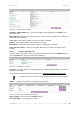
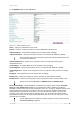
User’s Guide Version 1.0 Figure 103 – Edit DHCP Server Settings IP Address from/IP Address to – specify the IP address range supported for the DHCP service [mandatory fields]. WINS Address (Windows Internet Naming Service) – specify service IP address if it is available on the network [dots and digits]. Lease Time – specify the IP address renewal in seconds [1-1000000]. Domain – specify DHCP domain name [optional, 1-128 sting].
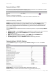
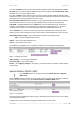
User’s Guide Version 1.0 Network Interface | POP3 It is convenient to use POP3 authentication way if there has no RADIUS server. BW1330 use POP3 interface to authenticate clients instead of RADIUS protocol. Figure 106 – POP3 Server configuration Just fill out the POP3 server IP address or URL name such like “mail.browan.com”. Network Interface | RADIUS RADIUS is an authentication and accounting system used by many Internet Service Providers (ISP).
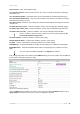
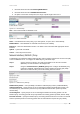
User’s Guide Version 1.0 NAS Server ID – name of the RADIUS client. User Session Timeout - amount of time from the user side (no network carrier) before closing the connection [sec]. User Accounting Update - period after which server should update accounting information [sec]. User Accounting Update Retry – retry time period in which server should try to update accounting information before giving up [sec].
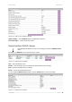
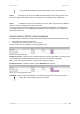
User’s Guide Version 1.0 Figure 109 – Apply or Discard RADIUS Settings Apply Changes – click if RADIUS settings configuration is finished. Discard Changes – restore all previous values. Network Interface | RADIUS | Servers Up to 32 different RADIUS servers can be configured under the RADIUS servers menu. By default, one RADIUS server is specified for the system: Figure 110 – RADIUS Servers Settings New – add new RADIUS server.
User’s Guide Version 1.0 To edit RADIUS server click the edit button: Figure 112 – Add New RADIUS Server Name – specify the new RADIUS server name. Default – check the check box to make the selected RADIUS the default server. Authentication IP – authentication RADIUS server IP address [dots and digits]. Authentication Port – specify the network port used to communicate with RADIUS [1-65535]. The port default value of 1812 is based on RFC 2138 "Remote Authentication Dialin User Service (RADIUS)".
User’s Guide Version 1.0 The value "disabled" means that Acct-Input* RADIUS attributes will contain bytes/packets sent to the client and Acct-Output* RADIUS attributes will contain bytes/packets received from the client during the curse of service being provided. The value "enabled" means that info in the Acct-Input* and Acct-Output* RADIUS attributes will be swapped (reversed).
User’s Guide Version 1.0 1. username follow the format: username@WISPdomain 2. username follow the format: WISPdomain/username 3. use prefix of username as wisp name, the range of prefix length is from 2 to 6. Figure 115 – Domain Policy New – click to define WISP for RADIUS server. Figure 116 – Define New WISP Name – new WISP domain name [string, up to 256 symbols, no space, dot or dash allowed]. RADIUS Name – select RADIUS for new WISP from list box [non editable].
User’s Guide Version 1.0 The authentication RADIUS proxy port should differ from the accounting port. Step 3 Configure the AP to send the RADIUS authentication and accounting packets to the AC LAN IP address and UDP ports which are configured on AC RADIUS proxy configuration. Step 4 The RADIUS secrets on AC should be set to value, which is good at the real RADIUS server for which the following packet will be forwarded.
User’s Guide Version 1.0 Network Interface | Tunnels This chapter describes the configuration of VPN tunnels. VPN tunnels can be used to secure management and AAA traffic between the hotspot network and the network operation center of the operator. The Access Controllers support GRE tunnels. Furthermore PPP (Point-to-Point Protocol) can be use to authenticate the AC to a authentication server and to assign IP settings to the WAN port of the AC.
User’s Guide Version 1.0 Network Interface | Tunnels | GRE Client for VPN GRE (Generic Routing Encapsulation) tunnel is one of the solutions for tunneling private network over the TCP/IP connection (e.g. PPTP, L2TP, PPPoE). GRE tunnel does not use encryption. It only encapsulates data and sends it over the Internet. So the administrator should take care that no unencrypted private information is going through the GRE tunnel.
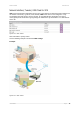
User’s Guide Version 1.0 For example, there are 2 internal networks: network A and B, and intermediate network - Internet. Network A (administrator's computer with Network Management System); we shall call this network (192.168.82.0/24) “Net A”. Network: 192.168.82.0 Netmask: 255.255.255.0 Router: 192.168.82.16 GRE server has two interfaces, LAN and WAN: LAN IP: 192.168.82.16 WAN IP: 211.139.210.123 Network B has subscribers on LAN of BW1330 interface (ixp0) we shall call this network (192.168.
User’s Guide Version 1.0 Network interface| wireless | Basic Use the Network interface | wireless | Basic menu to configure such wireless settings as regulatory domain, channel, band, and power, layer2isolation. Click the edit button on the setting to change the basic configuration of wireless module. 2.33 dBi 20 Figure 126 – Basic Wireless Settings Edit – edit the wireless basic settings To change basic wireless setting properties click the Edit button in the Action column.
User’s Guide Version 1.0 for a better performance. 2.4GHz (11g only) mode only allows 11g client access. 2.4GHz(Mixed 11g) mode allows 11b/11g client access.2.4GHz(Mixed 11g WiFi) or 2.4GHz(11g only WiFi) can make sure to compatible with Wi-Fi. Tx Power – the BW1330 transmission output power in dBm. Different power level is based on domain setting. Default is 18dBm&WORLD. Total Output Power (EIRP) = Antenna Gain + RF card output power The range of the EIRP varies with channel and regulatory domain.
User’s Guide Version 1.0 Reboot – Click the button to restart the server and apply the changes. And if there are still other setting modifications needed, go ahead to finish all changes and then click Reboot button to restart and apply all settings. Network interface | wireless | Advance BW1330 supports Multiple BSSID (MBSSID) function. You can configure up to 16 BSSIDs per radio on BW1330 and assign different configuration settings to each BSSID.
User’s Guide Version 1.0 Figure 131 – Multiple BSSID Setting Radio – showing which RF card, for BW1330 it is fixed: wlan1; Mode – showing the current operation mode, for BW1330 it is fixed: AP mode; SSID – a unique ID for your wireless network. It is case sensitive and must not exceed 32 characters. The SSID is important for clients when connecting to the access point. All client stations must have their client SSID settings configured and must use the same SSID.
User’s Guide Version 1.0 QoS – Quality of Service, stand for the priority of this SSID, the value of QoS is from 0 to 7, with the order: (1, 2, 0, 3, 4, 5, 6, 7), which 1 stand for the lowest priority which 7 stand for the highest priority. Security – Specify the security policy. WEP – When selected, the privacy of MSSID entry will be set to WEP (Wired Equivalent Privacy). WEP Key Index – Select the default key Index to make it the Default key and encrypt the data before being transmitted.
User’s Guide Version 1.0 Network Interface | Wireless | WDS A WDS (Wireless Distribution System) allows you to create a wireless network infrastructure. Normally the access points must be connected with a wired network (LAN), which is generally an Ethernet connection. Once connected, these access points create wireless cells allowing wireless connection to the wired network.
User’s Guide Version 1.0 Network interface | wireless | Sec WEP Use this menu to configure static WEP settings. This menu only set static WEP key value related with 4 key indexes for wireless module. Enable or Disable static WEP is in the Network interface | Wireless | Advance menu. Figure 134 – WEP Settings Radio – specify which interface is needed to be set. Click Edit to edit the existing WEP key1 to key4. By default, four WEP keys are all set to “aaaaa”. They can be modified according to real need.
User’s Guide Version 1.0 User Interface Use the user interface menu to configure device settings affecting the user interface. If you need to configure the: welcome/login/logout/help/unauthorized pages, administrator settings, start page or free sites, use the user interface menu. Figure 136 – User Interface Menu User Interface | Configuration | Pages Detailed description about user page customization is given in the Chapter 4 – User Pages.
User’s Guide Version 1.0 The redirect location URL should be specified as Walled Garden URL, otherwise the redirect would NOT WORK. Figure 139 – Caching Option Caching option can be used for caching the external uploaded user pages (available choice: enabled/disabled) Clear – click the button to clear cached user pages. Controller cache is also cleared after device reboot/reset.
User’s Guide Version 1.0 BW1330 automatically adds defined content-type and content-language to generated XML. Then user pages (.XSL) templates will use these parameters to generate the output HTML. Click the change button to define new headers of the web management interface on user pages templates. The default HTML encoding is ISO-8859-1, language = English.
User’s Guide Version 1.0 These features are aim to the facility of people who has no knowledge on XSL and replace the menu: user interface| Configuration| {pages, upload}. BW1330 support internal and external customized UAM. Internal means user can upload their html login and logout page to BW1330. External means BW1330 will go to an external web server to fetch login and logout page the local and push to web login client.
User’s Guide Version 1.0 Figure 147 – Upload pages Login File is for customized login page; Logout File is for customized logout page. Additional file 01~10 is for uploading picture and CSS files. Current support picture file format is JPG,GIF,PNG and CSS. Picture and CSS files name need be consistent with your login or logout html pages. The login and logout html file can be what ever you want. Don’t forget fill out the Logout page’s dimension.
User’s Guide Version 1.0 Figure 148 –Flash upload files OK After successful flash the files, uploaded files will appear in uploaded file list. Next is an example for customized login and logout page.
User’s Guide Version 1.0 Figure 150 –Example logout page For external pages, enabled the “use external page” in the first column of Customize Page Status: Enable Use External Page option and click edit button for the URL specify and save it then click done button to finish the setting. Figure 151 –External page configuration Fill out the external login page URL and external logout page URL. BW1330 would auto-update the external page every 7200 seconds or you change the interval update time.
User’s Guide Version 1.0 User Interface | Administrator The administrator menu is for changing the administrator’s settings: user name, password and session timeout: There are two kinds of administrator for BW1330: one is the super administrator and the other is the normal administrator or named ebilling administrator.
User’s Guide Version 1.0 Confirm Password – re-enter the new password to verify its accuracy. Save – click to save new administrator settings. Only super administrator can change the settings of super administrator and normal administrator. User Interface | Start Page The start page is the default web page where users will be redirected after log-on. This value will be overwritten by the WISP RADIUS attribute no.4 "Redirection-URL" if provided in the authentication response message.
User’s Guide Version 1.0 URL for User – define full URL address [ex:www.browan.com]. String to Display – site description. New Host – If you need to define hosts (web servers) for walled garden, specify hosts by clicking the new host button and click the update button: Figure 158 – Walled Garden Host Type –select the data traffic protocol for host server [TCP/UDP]. Host – Web server address [IP address or host name]. Netmask – enter the network mask to specify the host servers network.
User’s Guide Version 1.0 System Use the system menu to configure such system utilities: Syslog – for sending system and debug messages via the syslog protocol. Clock – manual setting of internal device clock. NTP – set the Network Time Protocol service on the AC. Certificates – upload your own SSL certificate and private key files for server. Save and Restore – save current AC configuration and restore.
User’s Guide Version 1.0 System | Configuration | Clock To set the Wireless PAC internal clock, use the clock utility, accessed by selecting the system | configuration | clock menu link: clock adjustment is allowed only when NTP is disabled. To adjust the clock settings, click the change button: Figure 163 – Clock Utility Figure 164 – Set Clock Settings Date – specify new date value [year/month/day]. Time – specify time [hours: minutes]. Time Zone – select the time zone [-12.00 – 14.00].
User’s Guide Version 1.0 Host – specify the trusted NTP server IP on the field. It works only with enabled NTP function. The NTP synchronize the device clock with GMT + 0 time. If you need to set the time zone, use the system | configuration | clock menu. You may want to add more than one NTP host, for example, in the case where the first host fails to connect. Click the new button to add additional host settings: Figure 167 – Add New NTP Host Host – add additional NTP service hosts [1-128].
User’s Guide Version 1.0 Certificate File – the PEM-encoded certificate file for the server. Corresponding RSA or DSA private keys SHOULD NOT be included. Private Key File – the PEM-encoded private key file for the server. Private key SHOULD NOT be encrypted with a password. This private key should correspond to the certificate above. Upload – upload new certificates.
User’s Guide Version 1.0 Figure 173 – Edit Configuration File Description Download – click the download once again to save the configuration file under the selected path in your computer. Now the last saved configuration is successfully stored in your local computer. Cancel – click the cancel button to back to main configuration page. You can use this file any time you want to restore this configuration to the device by using the upload button.
User’s Guide Version 1.0 Condition 1 and 2 can be met if operator applies a right certificate. We use Domain configuration on BW1330 to meet the condition 3. Please fill-out the domain name use the format such as a URL, for example: www.bw1330.com, which will be the same with the “host name” on the digital certificate. Create a new certificate with hostname = www.bw1330.com and then install on BW1330.
User’s Guide Version 1.0 Edit – click to edit the default access status [allow/deny]. New – click to create new access control rule for specific network to specific service(s) [all/ /ssh/telnet/snmp]. To configure the access control, click the edit button and specify the network address and select services to allow/deny: Figure 179 –Modify Access Control Service – select services that access you need to control [all/ssh/telnet/snmp].
User’s Guide Version 1.0 System | Access | Telnet When the telnet function is switched on, telnet connection to the Wireless PAC is enabled and the administrator can connect to the CLI interface via telnet. Make sure that default access status to the administrator PC appears as ‘allow’ under the system | access | access control menu. Otherwise, you will not be able to connect via telnet, even though the telnet function is enabled.
User’s Guide Version 1.0 When enabled 802.1x authentication in this menu, it will only take effect for the wired connection of the BVW1330. For wireless 802.1x authentication, please refer in Network interface | wireless | Advance section to enable 802.1x for wireless. Status – change status of selected AAA method [enabled/disabled].
User’s Guide Version 1.0 System | Access | Isolation Isolation mechanism under the system | access | isolation menu increases the security of the AC users. Figure 186 – Isolation Bindmac – with bindmac function enabled, the AC binds the user’s MAC and IP addresses together after a successful logon by the wireless client and thereby preventing Internet access to a new user who uses the same client IP address, although be it with a different MAC address [enabled/disabled].
User’s Guide Version 1.0 Figure 188– SNMP Settings SNMP Table: SNMP Service – enable or disable SNMP service on AC [enabled/disabled]. By default SNMP service is enabled. With service enabled the AC acts as the SNMP agent. If enabled, then device can be configured via SNMP: SNMP Name – An administratively assigned name for this managed node [0-99 any string]. By convention, this is the node’s fully qualified domain name. SNMP Location – The physical location of this node (e.g.
User’s Guide Version 1.0 SNMP Users – Users are used in SNMP version 3. They have the same access rights as communities, but instead of a single community name there are user name and password. Strong encryption is supported in SNMPv3. Figure 189 –SNMP user User Name – enter user name for read-only (RO) or read-write (RW) SNMP access [1-32 all ASCII printable characters, no spaces]. Password – enter password for read-only (RO) or read-write (RW) SNMP access [8-32 all ASCII characters, no spaces].