® CellPipe 7130 Residential Gateway 6Ve.A4111 & 6Vz.
Alcatel, Lucent, Alcatel-Lucent, the Alcatel-Lucent logo, and CellPipe are trademarks of Alcatel-Lucent. All other trademarks are the property of their respective owners. The information presented is subject to change without notice. Alcatel-Lucent assumes no responsibility for inaccuracies contained herein.
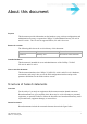
About this document Purpose This document provides information on the hardware setup, software configuration, and administration necessary to operate the CellPipe 7130 Residential Gateway 6Ve.A4111 and 6Vz.A4111. The 6Vz.A4111 supports HPNA; 6Ve.A4111 does not. Reason for revision The following table shows the revision history of this document.
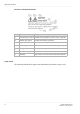
About this document ............................................................................................................................................................................................................................................................ Structure of hazard statements Item Structure element Purpose 1 Personal injury symbol Indicates the potential for personal injury (optional). 2 Hazard type symbol Indicates hazard type (optional).
About this document ............................................................................................................................................................................................................................................................ Signal words for hazard severity Signal word Meaning DANGER Indicates an imminently hazardous situation (high risk) which, if not avoided, will result in death or serious injury.
About this document ............................................................................................................................................................................................................................................................ ..............................................................................................................................................................................................................................................
Contents 1 Product overview Hardware introduction ............................................................................................................................... 1-1 Safety precautions ..................................................................................................................................... 1-2 Prerequisites ..............................................................................................................................................
Contents ............................................................................................................................................................................................................................................................ Demilitarized Zone (DMZ) ....................................................................................................................... 8-3 UPnP ...............................................................................................
Contents ............................................................................................................................................................................................................................................................ 12 Telephony Account Setup ..........................................................................................................................................12-1 Service Settings .............................................................
Contents ............................................................................................................................................................................................................................................................ .........................................................................................................................................................................................................................................................
1 Product overview Overview Purpose This chapter provides an introduction to the physical aspects of the CellPipe 7130 RG 6Ve.A4111 and 6Vz.A4111 including safety precautions, prerequisites, and descriptions. The CellPipe 7130 RG 6Ve.A4111 and 6Vz.A4111 will be referred to as CellPipe 7130 RG throughout the rest of this document.
Product overview Safety precautions ............................................................................................................................................................................................................................................................ The CellPipe 7130 RG also includes router and firewall functionality.
Product overview Prerequisites ............................................................................................................................................................................................................................................................
Product overview Description of LEDs and interfaces ............................................................................................................................................................................................................................................................ LED Status Description DSL 1 to 2 On DSL is operating. Flashing DSL is training. Off DSL is disconnected. On A device is connected to the USB port. Flashing USB port has data traffic.
Product overview Description of LEDs and interfaces ............................................................................................................................................................................................................................................................ Figure 1-2 Rear panel of 6Vz.A4111 Figure 1-3 Rear panel of 6Ve.A4111 Table 1-2 Rear panel items Item Description Wireless Antenna Antenna for transmission of wireless signal. ....................
Product overview Description of LEDs and interfaces ............................................................................................................................................................................................................................................................ Item Description VDSL port Input port of the VDSL network connection from your ISP. The VDSL port connects to a RJ-11 cable. Ethernet ports 1 to 4 Four RJ-45 ports to connect up to four PCs or Hub.
2 Hardware installation Overview Purpose This chapter provides the instructions to install the CellPipe 7130 RG hardware. Contents This chapter covers the following topic: Mounting Procedure 2-1 To install the CellPipe 7130 RG 2-2 Mounting Procedure There are multiple ways for mounting the CPE: Wall Mounting Pre-Requirements • Anchors • Screws • Drill & Drill bit 1. Locate a high position on the wall that is free of obstructions. 2. Connect two screws in the wall 5 cm(2 in.) apart.
Hardware installation To install the CellPipe 7130 RG ............................................................................................................................................................................................................................................................ 4. Hang up the CPE on the screws. Desktop Mounting Place the CPE on top of the desk with the rubber feet standing at the bottom.
Hardware installation To install the CellPipe 7130 RG ............................................................................................................................................................................................................................................................ Figure 2-1 Cable connections of 6Ve.A4111 & 6Vz.A4111 Procedure 1.
Hardware installation To install the CellPipe 7130 RG ............................................................................................................................................................................................................................................................ ..........................................................................................................................................................................................................
3 TCP/IP configuration Overview The following procedures provide TCP/IP configuration instructions for all supported operating systems. Windows 7 1. 2. 3. 4. 5. 6. 7. Open Network and Internet from the Control Panel. Open Network and Sharing Center from the Network and Internet. Right-click Local Area Connection from Network and Sharing Center. Under the General tab, select Internet Protocol (TCP/IPv4), and click Properties. Select the Obtain an IP address automatically radio button.
TCP/IP configuration Overview ............................................................................................................................................................................................................................................................ 3. Under the General tab, select Internet Protocol (TCP/IP), and click Properties. The Internet Protocol (TCP/IP) properties window appears. 4. Select the Obtain an IP address automatically radio button. 5.
4 Accessing the CellPipe 7130 RG web configuration tool Overview Purpose This chapter explains how to access the CellPipe 7130 RG web configuration tool by entering the IP address and the default passwords. The management interface software is HTML-based and can be accessed using a web browser.
Accessing the CellPipe 7130 RG web configuration tool To access the CellPipe 7130 RG web configuration tool ............................................................................................................................................................................................................................................................
Accessing the CellPipe 7130 RG web configuration tool To access the CellPipe 7130 RG web configuration tool ............................................................................................................................................................................................................................................................ Figure 4-2 Status window The status window is described in Chapter 5, “Status”.
Accessing the CellPipe 7130 RG web configuration tool To access the CellPipe 7130 RG web configuration tool ............................................................................................................................................................................................................................................................ ....................................................................................................................................................
5 Status Overview Purpose This chapter describes the contents of the Status menu, which contains the status information for the CellPipe 7130 RG, its connections, and the connected hardware. Click the Status drop-down menu to open the Status menu.
Status System Usage ............................................................................................................................................................................................................................................................ Figure 5-1 System Usage window Table 5-1 describes the fields of the System Usage window. Table 5-1 Field descriptions Field Description Version Info Model Name The model name of the modem.
Status WAN PTM Status ............................................................................................................................................................................................................................................................ Field Description 1 to 10 Number: The status (Enabled or Disabled) of accounts 1 to 10. Network - LAN Status LAN IP Address The IP address of the LAN interface. LAN NetMask The subnet mask of the LAN interface.
Status DSL Link Status ............................................................................................................................................................................................................................................................ Field Description Netmask The subnet mask of the IP address. Gateway The IP address of gateway. DNS 1 to 3 The IP address of Domain Name Server.
Status DSL Link Status ............................................................................................................................................................................................................................................................ Table 5-3 Field descriptions Field Description DSL Firmware Version The version of firmware in use. Mode The modulation protocol Traffic Type The channel type Status This is the status of the DSL link.
Status Device Table ............................................................................................................................................................................................................................................................ Field Description INP (DMT symbol) INP:Impulse Noise Protection DMT:Discrete Multitone OH Frames The number of overhead frames. OH Frame Errors The number of overhead frame errors.
Status DHCP Lease ............................................................................................................................................................................................................................................................ Figure 5-4 Device Table window Table 5-4 describes the fields of the Device Table window. Table 5-4 Field descriptions Field Description Host Name The name of the device that has connected to the gateway.
Status WiFi Associate ............................................................................................................................................................................................................................................................ Field Description Host Name The host name of the DHCP client computer. Vendor Class Identifier The DHCP client platform. Expiry The time left before this lease expires.
Status WAN/(W)LAN Statistics ............................................................................................................................................................................................................................................................ Figure 5-7 WAN/(W)LAN Statistics window Table 5-7 describes the WAN, LAN, and WLAN fields of the Statistics window. Table 5-7 Field descriptions Field Description RX bytes The number of bytes that have been received.
Status IGMP Membership ............................................................................................................................................................................................................................................................ Field Description TX Errors The number of packets that have been transmitted with errors. TX Dropped The number of packets that have been dropped after transmitting.
Status IGMP Statistic ............................................................................................................................................................................................................................................................ Select IGMP Statistic in the Status menu to access the IGMP Membership windows; see Figure 5-9. Figure 5-9 IGMP Statistic window Table 5-9 describes the IGMP Statistic window.
Status IGMP Statistic ............................................................................................................................................................................................................................................................ ..........................................................................................................................................................................................................................................
6 Network Overview Purpose This chapter explains how to configure the network settings for the CellPipe 7130 RG from the Network menu. Click the Network drop-down menu to open the Network menu. Contents This chapter covers the following topics: USB 6-1 LAN Setting 6-2 WAN PTM Connections 6-4 USB The USB window enables you to configure the USB storage name, USB printer name and DMS. Select USB in the Network menu to access the USB&DMS window; see Figure 6-1. .......................................
Network LAN Setting ............................................................................................................................................................................................................................................................ Figure 6-1 USB window Table 6-1 describes the fields of the USB window. Table 6-1 Field descriptions Field Description USB Printer Enable Click the radio button to enable or disable USB Printer.
Network LAN Setting ............................................................................................................................................................................................................................................................ Figure 6-2 LAN Setting window Table 6-2 describes the fields of the LAN Setting window. Table 6-2 Field descriptions Field Description IP Address The IP address of the LAN interface in dotted decimal notation. The default is 192.
Network WAN PTM Connections ............................................................................................................................................................................................................................................................ Field Description Subnet Mask The subnet mask of the IP addresses in your LAN; for example, 255.255.255.0.
Network WAN PTM Connections ............................................................................................................................................................................................................................................................ Select WAN PTM Connections in the Network menu to access the WAN PTM Connections window; see Figure 6-3. Figure 6-3 WAN PTM Connections window Table 6-3 describes the fields of the WAN PTM Connection window.
Network WAN PTM Connections ............................................................................................................................................................................................................................................................ Field Description CMWP (CPE WAN Management Protocol) Provide remote control service. It will allow remote ACS server to manage this gateway.
Network WAN PTM Connections ............................................................................................................................................................................................................................................................ Figure 6-4 Static IP settings window with Port Based Binding Table 6-4 describes the fields of the Static IP setting window with Port Based Binding.
Network WAN PTM Connections ............................................................................................................................................................................................................................................................ Field Description Options MTU Select Auto to set the maximum transfer unit to the default (1500), or select Manual to manually enter a value. Next Click to go to next step. Back Click to go back to previous page.
Network WAN PTM Connections ............................................................................................................................................................................................................................................................ Figure 6-5 DHCP settings window with Port Based Binding Table 6-5 describes the fields of the DHCP Mode setting window with Port Based Binding.
Network WAN PTM Connections ............................................................................................................................................................................................................................................................ Field Description Host Name Enter the appropriate Host Name and Domain Name provided by your ISP. If you are not sure, please consult with your ISP for more information.
Network WAN PTM Connections ............................................................................................................................................................................................................................................................ Figure 6-6 PPPoE Mode settings window with Port Based Binding Table 6-6 describes the fields of PPPoE Mode setting window with Port Based Binding.
Network WAN PTM Connections ............................................................................................................................................................................................................................................................ Fields Description Password Enter the password for the PPPoE connection.If you are not sure, please consult with your ISP for more information. Access Concentrator The access concentrator is optional.
Network WAN PTM Connections ............................................................................................................................................................................................................................................................ Figure 6-7 Bridge Mode settings window with Port Based binding Table 6-7 describes the fields of the Bridge Mode setting window with Port Based binding.
Network WAN PTM Connections ............................................................................................................................................................................................................................................................ Fields Description Back Click to back preview page. Activate WAN Settings Click to activate the connection. Delete All Click to remove all WAN connections. Edit Click to modify a specific connection.
Network WAN PTM Connections ............................................................................................................................................................................................................................................................ Figure 6-8 DHCP settings window Table 6-8 describes the fields of the DHCP Mode setting window. Table 6-8 Field descriptions Fields Description LAN Binding Default The first rule must be the default.
Network WAN PTM Connections ............................................................................................................................................................................................................................................................ Fields Description Destination MAC Select the radio button and enter the applicable Destination MAC address in hexadecimal format. WAN VLAN Select Untagged if VLAN tagging is not to be used for this WAN connection.
Network WAN PTM Connections ............................................................................................................................................................................................................................................................ Figure 6-9 WAN PTM Connections window with MAC based binding After you have a default connection, you can choose the WAN Mode you want and click Add to add a new connection.
Network WAN PTM Connections ............................................................................................................................................................................................................................................................ Figure 6-10 Bridge Mode settings window with MAC based binding Table 6-9 describes the fields of Bridge Mode setting window with MAC based binding.
Network WAN PTM Connections ............................................................................................................................................................................................................................................................ Fields Description VLAN Select Untagged if VLAN tagging is not to be used for this WAN connection. Select Always use ID if VLAN tagging is to be used and enter the VLAN ID number (between 0 and 4094).
Network WAN PTM Connections ............................................................................................................................................................................................................................................................ Figure 6-11 WAN PTM Connections window with MAC based binding You can only choose Bridge mode with MAC based binding and you can select Static IP, DHCP, or PPPoE with No LAN/WLAN Binding for CWMP and VoIP.
Network WAN PTM Connections ............................................................................................................................................................................................................................................................ Figure 6-12 Static IP settings window with No LAN/WLAN Binding Table 6-10 describes the fields of Static IP setting window with No LAN/WLAN Binding.
Network WAN PTM Connections ............................................................................................................................................................................................................................................................ DHCP Mode If you select DHCP as the mode and click Add, the DHCP window with No LAN/WLAN Binding opens; see Figure 6-13.
Network WAN PTM Connections ............................................................................................................................................................................................................................................................ Field Description MTU (Bytes) Enable Auto to set the maximum transfer unit to the default (1500), or enable Manual to manually enter a value. Next Click to go to next step. Back Click to go back to preview page.
Network WAN PTM Connections ............................................................................................................................................................................................................................................................ Fields Description Untagged Select this option if VLAN ID is not being used.
Network WAN PTM Connections ............................................................................................................................................................................................................................................................ QoS Defaults The QoS Defaults window enables you to configure the default QoS policy for each WAN connection, see Figure 6-15. Figure 6-15 QoS Defaults window Table 6-13 describes the fields of the QoS Defaults window.
Network WAN PTM Connections ............................................................................................................................................................................................................................................................ Field Description New ToS Value Select New Tos Value and enter a queue number (0 to 7) to assign to the network traffic. New DSCP Value Select New DSCP Value and enter a DSCP value (0 to 63).
7 WiFi Setup Overview Purpose This chapter explains how to configure the WiFi settings for the CellPipe 7130 RG from the WiFi setup menu. Click the WiFi Setup drop-down menu to open the WiFi Setup menu. Contents This chapter covers the following topics: WiFi Setting 7-1 WiFi Security 7-4 WiFi Access Filter 7-6 WiFi Setting The WiFi Setting window enables you to configure the common wireless and SSID settings.
WiFi Setup WiFi Setting ............................................................................................................................................................................................................................................................ Figure 7-1 WiFi Setting window Table 7-1 describes the fields of the WiFi Setting window. Table 7-1 Field descriptions Field Description Common WiFi Select Enable to turn wireless on and configure the wireless settings.
WiFi Setup WiFi Setting ............................................................................................................................................................................................................................................................ Field Description Tx Power Enter a value between 1~100 to control the level of transmitting signal strength. Radio Mode Click the drop-down menu and select either b/g/n, b/g, g/n, b, g or n for the wireless mode.
WiFi Setup WiFi Security ............................................................................................................................................................................................................................................................ Notes: 1 If you enable WDS, check that all other WDS APs are enabled, configured with the same channel, SSID, and encryption keys, and that each AP has a different LAN port IP address.
WiFi Setup WiFi Security ............................................................................................................................................................................................................................................................
WiFi Setup WiFi Access Filter ............................................................................................................................................................................................................................................................ WiFi Access Filter The WiFi Access Filter window enables you to either block or permit access for wireless clients by MAC address.
WiFi Setup WiFi Access Filter ............................................................................................................................................................................................................................................................ Field Description MAC 1 to 32 Enter up to 32 MAC addresses to control their access. Apply Changes Click to save your changes. ..............................................................................................
WiFi Setup WiFi Access Filter ............................................................................................................................................................................................................................................................ ..................................................................................................................................................................................................................................
8 Firewall Setup Overview Purpose This chapter explains how to configure the firewall for the CellPipe 7130 RG. Click the Firewall drop-down menu to open the Firewall Setup menu.
Firewall Setup Port Forwarding ............................................................................................................................................................................................................................................................ Select Port Forwarding in the Firewall Setup menu to access the Port Forwarding window; see Figure 8-1. Figure 8-1 Port Forwarding window Table 8-1 describes the fields of the Port Forwarding window.
Firewall Setup Demilitarized Zone (DMZ) ............................................................................................................................................................................................................................................................
Firewall Setup UPnP ............................................................................................................................................................................................................................................................ Figure 8-2 Demilitarized Zone window Table 8-2 describes the fields of the Demilitarized Zone window. Table 8-2 Field descriptions Field Description Demilitarized Zone (DMZ) Select Enable to turn on the demilitarized zone function.
Firewall Setup Layer 2 Filter ............................................................................................................................................................................................................................................................ Select UPnP in the Firewall Setup menu to access the UPnP window; see Figure 8-3. Figure 8-3 UPnP window Table 8-3 describes the fields of the UPnP window.
Firewall Setup Layer 2 Filter ............................................................................................................................................................................................................................................................ Figure 8-4 Layer 2 Filter window Table 8-4 describes the fields of the Filter window.
Firewall Setup Layer 3 Filter ............................................................................................................................................................................................................................................................ Field Description Source Mac Address 1 to 10 Select and then enter the source MAC address of the device. Destination Mac Address 1 to 10 Select and then enter the destination MAC address of the device.
Firewall Setup NAT Passthrough ............................................................................................................................................................................................................................................................ Field Description IP Address Enter the IP address of the host that you are blocking. IP Netmask Select the Netmask of the host that you are blocking.
Firewall Setup URL Blocking ............................................................................................................................................................................................................................................................ Figure 8-6 NAT Passthrough window Table 8-6 describes the fields of the NAT Passthrough window. Table 8-6 Field descriptions Field Description IPSec Passthrough Select Enable to allow IPSec passthrough.
Firewall Setup Content Screening ............................................................................................................................................................................................................................................................ Figure 8-7 URL Blocking window Table 8-7 describes the fields for the URL Blocking window. Table 8-7 Field descriptions Field Description Name Enter a name for this URL filter.
Firewall Setup Content Screening ............................................................................................................................................................................................................................................................ Figure 8-8 Content Screening window Table 8-8 describes the fields for the Content Screening window.
Firewall Setup Parental Control ............................................................................................................................................................................................................................................................ Parental Control The Parental Control window enables you to limit your computer’s Internet connection based on the time and day of the week.
Firewall Setup Parental Control ............................................................................................................................................................................................................................................................ Field Description Time Enter a time period (in hours and minutes) to limit the Internet connection. Add Click to add rule in Parental control. ...........................................................................
Firewall Setup Parental Control ............................................................................................................................................................................................................................................................ ................................................................................................................................................................................................................................
9 Advanced Setup Overview This chapter explains how to configure the advanced settings of the CellPipe 7130 RG such as the route setting, DNS, dynamic DNS, system log, IGMP settings and 802.1x. Click the Advanced Setup drop-down menu to open the Advanced Setup menu. Contents This chapter covers the following topics: Route Setting 9-1 DNS Settings 9-3 Dynamic DNS 9-4 System Log 9-5 IGMP Proxy/Snooping 9-6 802.
Advanced Setup Route Setting ............................................................................................................................................................................................................................................................ Figure 9-1 Route Setting window Table 9-1 describes the fields of the Route Setting window.
Advanced Setup DNS Settings ............................................................................................................................................................................................................................................................ Field Description Dynamic Route (WAN) Select Enable to use dynamic routing instead of static. Dynamic routing enables the router to adapt to changes in the network and exchange rating table with other router(s).
Advanced Setup Dynamic DNS ............................................................................................................................................................................................................................................................ Dynamic DNS The Dynamic DNS (DDNS) window enables you to configure your registered domain name with a dynamic IP address.
Advanced Setup System Log ............................................................................................................................................................................................................................................................ System Log The System Log window enables you to view the system logs and to send them to a remote system log server. Click on System Log in the Advanced Setup menu to access the system log window; see Figure 9-4.
Advanced Setup IGMP Proxy/Snooping ............................................................................................................................................................................................................................................................ Field Description Level The level of logging activity: • • • Message Info Error Debug The details of the action that was performed.
Advanced Setup 802.1x Config ............................................................................................................................................................................................................................................................ Table 9-5 Field descriptions Field Description IGMP Enable Select Enable to allow IGMP support. Select Disable to disable IGMP support. Port Enable Enable/Disable IGMP support for each individual LAN port.
Advanced Setup 802.1x Config ............................................................................................................................................................................................................................................................ Field Description Apply Changes Click to save your changes. ...................................................................................................................................................................
10 QoS PTM Setup Overview This chapter explains how to configure the QoS settings via PTM. QoS is the ability to provide better service to selected applications and data flows. Click the QoS PTM Setup drop-down menu to open the QoS PTM Setup menu. Contents This chapter covers the following topics: QoS Overview 10-1 QoS Scheduler 10-2 QoS Policy 10-4 QoS Phone 10-7 QoS ALG 10-9 QoS Defaults 10-11 QoS MAC 10-13 QoS Overview The QoS overview window allows you to see all current QoS settings.
QoS PTM Setup QoS Scheduler ............................................................................................................................................................................................................................................................ Figure 10-1 QoS Overview window Table 10-1 describes the fields of the QoS overview window. Table 10-1 Field descriptions Field Description Precedence The Precedence presents the priority of each QoS rule.
QoS PTM Setup QoS Scheduler ............................................................................................................................................................................................................................................................ Figure 10-2 QoS Scheduler window Table 10-2 describes the fields of the QoS Scheduler window. Table 10-2 Field descriptions Field Description QoS Enable Select Enable to activate the QoS scheduler.
QoS PTM Setup QoS Policy ............................................................................................................................................................................................................................................................ Field Description 4. Low Specify the minimum and maximum bandwidth for the Low queue. 3. Premium Specify the minimum and maximum bandwidth for the Premium queue. 2.
QoS PTM Setup QoS Policy ............................................................................................................................................................................................................................................................ Figure 10-3 QoS Policy window Table 10-3 describes the fields of the QoS Policy window. Table 10-3 Field descriptions Field Description Source IP Address Select the radio button and enter the IP address of the source host. ..
QoS PTM Setup QoS Policy ............................................................................................................................................................................................................................................................ Field Description Netmask Select the subnet mask of the source host. Interface Select the radio button and select a connection to configure its QoS policy. MAC Address Select the radio button and enter the MAC address.
QoS PTM Setup QoS Phone ............................................................................................................................................................................................................................................................ Field Description Protocol The protocol type for this QoS policy. Priority The priority queue (0 to 7) used by the traffic. CoS CoS value of the QoS policy. ToS/DSCP ToS/DSCP marking setting for incoming traffic.
QoS PTM Setup QoS Phone ............................................................................................................................................................................................................................................................ Figure 10-4 QoS Phone window Table 10-4 describes the fields of the QoS Phone window. Table 10-4 Field descriptions Field Description SIP Sessions Check DSCP Value (Diffserv Code Point) and enter a DSCP value (0 to 63).
QoS PTM Setup QoS ALG ............................................................................................................................................................................................................................................................ QoS ALG The QoS application level gateway (ALG) window enables you to configure the session initiated protocol (SIP) and the real-time transport protocol (RTP).
QoS PTM Setup QoS ALG ............................................................................................................................................................................................................................................................ Figure 10-5 QoS ALG window ..............................................................................................................................................................................................................
QoS PTM Setup QoS Defaults ............................................................................................................................................................................................................................................................ Table 10-5 describes the fields of the QoS ALG window. Table 10-5 Field descriptions Field Description SIP ALG QoS Enable Select Enable to turn on the SIP ALG QoS. Select Disable to turn off the SIP ALG QoS.
QoS PTM Setup QoS Defaults ............................................................................................................................................................................................................................................................ Figure 10-6 QoS Defaults window Table 10-6 describes the fields of the QoS Default window. Table 10-6 Field descriptions Field Description Interface Select a WAN connection to configure its default QoS policy.
QoS PTM Setup QoS MAC ............................................................................................................................................................................................................................................................ Field Description New Tos Value Select New Tos Value and enter a queue number (0 to 7) to assign to the incoming traffic. New DSCP Value Select New DSCP Value and enter a DSCP value (0 to 63).
QoS PTM Setup QoS MAC ............................................................................................................................................................................................................................................................ Figure 10-7 QoS MAC window Table 10-7 describes the fields of the QoS ALG window. Table 10-7 Field descriptions Field Description Bridge Destination MAC Address Specify the MAC address of QoS service user.
11 Utilities Overview This chapter explains how to configure the utilities of the CellPipe 7130 RG. Click the Utilities drop-down menu to open the Utilities menu. Contents This chapter covers the following topics: Configuration Backup 11-1 Configuration Restore 11-2 Firmware Upgrade 11-3 System Setting 11-4 Management Access Control 11-7 CWMP Management 11-8 Connection Test 11-9 802.
Utilities Configuration Restore ............................................................................................................................................................................................................................................................ Figure 11-1 Configuration Backup window Click on Backup to save your system configuration.
Utilities Firmware Upgrade ............................................................................................................................................................................................................................................................ Table 11-1 Field descriptions Field Description Restore Configuration Click Browse and select a configuration backup file to restore. Restore Click to restore the configuration.
Utilities System Setting ............................................................................................................................................................................................................................................................ Table 11-2 Field descriptions Field Description Update Firmware Click Browse to locate and select the firmware upgrade file to upload. Firmware upgrades are available at http://www.alcatel-lucent.com/wps/portal/support.
Utilities System Setting ............................................................................................................................................................................................................................................................ Figure 11-4 System Setting window Table 11-3 describes the fields of the System Setting window. Table 11-3 Field descriptions Field Description GUI Setting Administrator Login Enter a new username for administrator. .........
Utilities System Setting ............................................................................................................................................................................................................................................................ Field Description Administrator Password Enter the current admin password. Note: If this is the first time the admin password is changed, the default admin password is admin. Administrator New Password Enter a new password.
Utilities Management Access Control ............................................................................................................................................................................................................................................................ Management Access Control The Management Access Control window enables you to control who can access the service provided by the gateway. Note: It is recommended that you consult your ISP before configuring the access.
Utilities CWMP Management ............................................................................................................................................................................................................................................................ Field Description Firewall Stealth Mode Select Enable to allow firewall to drop all Stealth or unknown traffic. Select Disable to accept all unknown traffic. Apply Changes Click to save your changes.
Utilities Connection Test ............................................................................................................................................................................................................................................................ Field Description ACS User Name Enter the username of the auto-configuration server. ACS Password Enter the password for the auto-configuration server.
Utilities 802.1x CA Upload ............................................................................................................................................................................................................................................................ Figure 11-7 Connection Test window Table 11-6 describes the fields of the Connection Test window.
Utilities Restore Factory Defaults ............................................................................................................................................................................................................................................................ Figure 11-8 802.1x CA Upload window Table 11-7 describes the fields of the 802.1x CA Upload window.
Utilities Reboot Gateway ............................................................................................................................................................................................................................................................ Reboot Gateway The Reboot Gateway window enables you to reboot the CellPipe 7130 RG. Rebooting the gateway does not reset your settings.
12 Telephony Overview The CellPipe 7130 RG Telephony menu enables you to configure the settings for your VoIP account and view the calling log. Click the Telephony drop-down menu to open the Telephony menu. Contents This chapter covers the following topics. Account Setup 12-1 Service Settings 12-3 SIP Server Settings 12-7 RTP/Codec settings 12-9 Account & Line Table 12-11 Call History 12-11 Other Settings 12-12 Account Setup Your VoIP account settings can be configured here.
Telephony Account Setup ............................................................................................................................................................................................................................................................ Figure 12-1 Account Setup window Table 12-1 describes the fields of the Account Setup window. Table 12-1 Field descriptions Field Description Configuration of Account Select to configure a VoIP account. ........................
Telephony Service Settings ............................................................................................................................................................................................................................................................ Field Description Enable this Account Enable the check box to enable the account registered to the SIP of the VoIP service provider. Phone Number Enter the account’s phone number.
Telephony Service Settings ............................................................................................................................................................................................................................................................ Figure 12-2 Service Settings window ................................................................................................................................................................................................
Telephony Service Settings ............................................................................................................................................................................................................................................................ Table 12-2 describes the fields of the Service Setting window. Table 12-2 Field descriptions Field Description Hide Calling Identity (Per call) The activation code for hiding your account’s information when making a call.
Telephony Service Settings ............................................................................................................................................................................................................................................................ Field Description Warm Line destination Enter a phone number for as warm line’s destination.
Telephony SIP Server Settings ............................................................................................................................................................................................................................................................ Field Description Unconditional Service Code Activate The activation code for your “Unconditional Call Forwarding” service. Deactivate The deactivation code for your “Unconditional Call Forwarding” service.
Telephony SIP Server Settings ............................................................................................................................................................................................................................................................ Figure 12-3 SIP Server Setting window Table 12-3 describes the fields of the Server Setting window. Table 12-3 Field descriptions Field Description Registrar Server Enter the location of the SIP registration server.
Telephony RTP/Codec settings ............................................................................................................................................................................................................................................................ RTP/Codec settings The RTP/Codecs settings window allows you to setup the codecs and ports for your voice traffic. Select RTP/Codecs settings in the Telephony menu to access the RTP/Codecs window; see Figure 12-4.
Telephony RTP/Codec settings ............................................................................................................................................................................................................................................................ Table 12-4 Field descriptions Field Description Primary Codec A codec (coder/decoder) codes analog voice signals into digital signals and decodes the digital signals back into analog voice signals.
Telephony Account & Line Table ............................................................................................................................................................................................................................................................ Account & Line Table The Account & Line Table enables you to specify which VoIP accounts are associated with your phone ports/lines.
Telephony Other Settings ............................................................................................................................................................................................................................................................ Figure 12-6 Call History window Table 12-6 describes the fields of the Call History window. Table 12-6 Field descriptions Field Description VoIP Account Please select to display the call logs for the specified VoIP accounts.
Telephony Other Settings ............................................................................................................................................................................................................................................................ Figure 12-7 Other Settings window Table 12-7 describes the fields of the Other Settings window. Table 12-7 Field descriptions Field Description Country Select a country from the list.
Telephony Other Settings ............................................................................................................................................................................................................................................................ .......................................................................................................................................................................................................................................
13 USB Service Overview This chapter explains how to setup USB devices on CellPipe 7130 RG. Note: USB hub is also supported Contents This chapter covers the following topics: File sharing 13-1 Printer Server 13-4 File sharing The CellPipe 7130 RG allows you to share files on USB storage devices.
USB Service File sharing ............................................................................................................................................................................................................................................................ Note: The address 192.168.2.1 is your LAN management IP. It can be changed by user configuration. END OF STEPS ........................................................................................................................
USB Service File sharing ............................................................................................................................................................................................................................................................ Figure 13-1 File sharing END OF STEPS ........................................................................................................................................................ Mac OS 1.
USB Service Printer Server ............................................................................................................................................................................................................................................................ Printer Server CellPipe 7130 RG can also be a printer server. The configuration steps is described below: Windows 1. Plug the USB printer into the CellPipe 7130 RG USB port. 2. Open Windows setting. 3.
USB Service Printer Server ............................................................................................................................................................................................................................................................ Figure 13-3 Printer setting on Mac END OF STEPS ........................................................................................................................................................ .........................
USB Service Printer Server ............................................................................................................................................................................................................................................................ .....................................................................................................................................................................................................................................
14 FCC and IC Statement Overview This section lists the product conformance requirements. Federal Communication Commission Interference Statement This equipment has been tested and found to comply with the limits for a Class B digital device, pursuant to Part 15 of the FCC Rules. These limits are designed to provide reasonable protection against harmful interference in a residential installation.
FCC and IC Statement FCC Part 68 Statement ............................................................................................................................................................................................................................................................ IMPORTANT NOTE: FCC Radiation Exposure Statement: This equipment complies with FCC radiation exposure limits set forth for an uncontrolled environment.
FCC and IC Statement Industry Canada statement ............................................................................................................................................................................................................................................................ Company: Alcatel-Lucent Address: 600-700 Mountain Avenue Murry Hill, NJ 07974 Tel no.
FCC and IC Statement IC TELECOM ............................................................................................................................................................................................................................................................ IC TELECOM ''NOTICE: This equipment meets the applicable Industry Canada Terminal Equipment Technical Specifications. This is confirmed by the registration number.
A Troubleshooting Overview This section identifies common problems that can arise during the use of the CellPipe 7130 RG and offers solutions. Most issues are identified by the LEDs on the front panel of the CellPipe 7130 RG. Troubleshooting Table Symptom Possible cause Solution Power LED does not come on after power is switched on. Outlet, power cord, or power adapter might be defective. • • VDSL Link LED flashes slowly after connection is established then it quickly stats to flash slowly again.
Troubleshooting Overview ............................................................................................................................................................................................................................................................ Symptom Possible cause Solution Message LED is flashing. A firmware upgrade is in progress. • • Intenet LED is off. Your CellPipe 7130 RG is unable to connect to the Internet or CellPipe 7130 RG is not power on.
B Product conformance Overview This section lists the product conformance requirements for the EU. EU declaration of conformity This device complies with the essential requirements of the R&TTE Directive 1999/5/EC.
Product conformance EU declaration of conformity ............................................................................................................................................................................................................................................................ This device is a 2.4 GHz wideband transmission system (transceiver), intended for use in all EU member states and EFTA countries, except in France and Italy where restrictive use applies.
Glossary Numerics 10/100Base-T The most widely used standard for Ethernet over twisted pair or copper-based computer networking. Runs at 10 Mb/s, 100 Mb/s, and 1000 Mb/s (1 Gb/s) respectively. 802.1 Q/P The standard that allows multiple bridged networks to transparently share the same physical network link without leakage of information between networks.
Glossary ............................................................................................................................................................................................................................................................
Glossary ............................................................................................................................................................................................................................................................ L L2TP Layer 2 tunneling protocol; a tunneling protocol used to support virtual private networks (VPNs). LAN Local Area Network M MAC Media Access Control Mb Megabit; a unit of information commonly used to express the rate data is transferred.
Glossary ............................................................................................................................................................................................................................................................ PSK Pre-Shared Key Q QoS Quality of Service R RJ-11 A physical interface often used for terminating telephone wires. RJ-45 Most regularly used as an Ethernet connector. RJ-45 connectors are typically used to terminate twisted pair cable.
Glossary ............................................................................................................................................................................................................................................................
Glossary ............................................................................................................................................................................................................................................................ .........................................................................................................................................................................................................................................................