Document Number Created By Eric GIoT Femto Cell User Guide Modification History Date Change log Author Revision 2017/3/23 1st version Eric, Joey 001 This GIoT Femto Cell User Guide will assist you in navigating the system with the
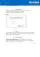
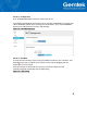
following comprehensive guidelines. 1. Open Admin GUI Connect to Femto Cell via wifi (SSID: AP-last 6 numbers of mac address) Access Femto Cell WebUI via IP address “192.168.55.1”. Default username is “admin” and password is "admin“. Figure 1 2. Status The Status menu consists of the following categories: Overview, Routes, System Log, Kernel Log, Processes and Realtime Graphs. An introduction of each category will be distinctly stated in individual paragraphs. 2.
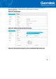
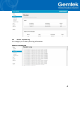
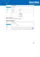
An “AUTO REFRESH ON/OFF” button is lodged on the top right of the panel. This function enables the status data to be refreshed every 5 seconds. (figure3.A & figure3.B) Figure 2.A - System Status Figure 2.B - Memory Usage and Network Settings Figure 3.
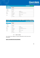
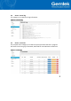
Figure 3.B - Click “AUTO REFRESH ON/OFF” button to enable/ disable auto refresh. 2.2 Status - Routes The purpose of this category is to view the ARP table and active IPv4 routes information.
2.3 Status - System Log This category is to view system log information.
2.4 Status - Kernel log This category is to view kernel log information. Figure 6 - Kernel Log 2.5 Status - Processes The purpose of this category is to view the system processes that are in progress. Processes can be hung up, terminated, and killed for each indivFemto Cellal item.
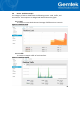
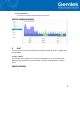
2.6 Status - Realtime Graphs This category is further divided into the following sectors: Load, Traffic, and Connections. These options are lodged and labeled above the graph. 2.6.1 Load To view the current load value and average of different time intervals. Figure 8 - Realtime Load 2.6.2 Traffic To view the network traffic of each interface.
2.6.3 Connections To view the currently active network connections. Figure 10 - Realtime Connections 3. GIoT The GIoT menu consists of the following categories: Status, Provision, Configuration and GPS MAP. 3.1 GIoT - Status The purpose of this category is to view GIoT information as in its provision code, gateway type, gateway ID or LoRa modules, channels, spreading factor, and GPS status.
3.2 GIoT - Provision GIoT provision code can be setup on this page.
3.3 GIoT - Configuration Click “PERFORM RESTART” button to restart LoRa server. The latitude and longitude coordinates can be manually embedded in this page. Click “SAVE LOCATION” button after inserting the coordinates or click “SELECT ON MAP” button to be redirected to the map in GPS Settings. Figure 13 - GIoT Management 3.
10
4. LoRaWan The LoRaWan menu consists of the following categories: OTAA Status, OTAA, ABP and Network Server. The proper provision code has to be in place to reveal and access the LoRaWan features on the system menu. Please contact GIoT personnel if needed. 4.1 LoRaWan - OTAA Status The purpose of this feature is to view the process status of a node joining Femto Cell via OTAA. Figure 15 - OTAA Status 4.2 LoRaWan - OTAA Click “ADD” button to create an OTAA rule entry.
Figure 16.B - OTAA Figure 16.C - OTAA - Edit 4.
The main function of this feature is to add/delete/edit ABP rule entries on this page. The ABP menu consists of the following categories: Individual and NetID Group. 4.3.1 INDIVIDUAL Click “INDIVIDUAL” button to enter the INDIVIDUAL function page. Click “ADD” button to create an ABP (INDIVIDUAL) rule entry. To delete rule entries, select one or more ABP (INDIVIDUAL) rule entries and click “DELETE” button. To edit a rule entry , select an ABP (INDIVIDUAL) rule entry and click “EDIT” button to proceed.
Figure 17.A - Individual Figure 17.B - Individual – Add Figure 17.C - Individual – Edit 4.3.2 NETID GROUP Click “NETID GROUP” button to enter NETID GROUP function page. Click “ADD” button to create a ABP (NETID GROUP) rule entry. To delete rule entries, select one or more ABP (NETID GROUP) rules and click “DELETE” button.
To edit a rule entry, select a ABP (NETID GROUP) rule entry and click “EDIT” button to proceed. Please note that the ABP (NETID GROUP) settings will be cleared after Femto Cell is reset to default.
Figure 18.A - NETID GROUP Figure 18.B - NETID GROUP - ADD Figure 18.C - NETID GROUP - EDIT 4.4 LoRaWan - Network Server The user can configure Network Server settings on this page. The Femto Cell connects to the lora data center via CURL or MQTT. Note that the node data will be sent to Gemtek lora data center if you select CURL.
17
5. System The System menu consists of the following categories: System, Administration, Backup, System Firmware, Reboot. Introduction and input procedures for each category are described in the following paragraphs. 5.1 System - System Hostname and Timezone can be customized in the system properties. Click “Sync with Browser” button (figure20.A) to adjust the local time. Place a checkmark next to “Enable NTP Client” (figure20.B) to synchronize the time with NTP server.
19
5.2 System - Administration Gateway login password and SSH accessibility can be configured in this page. Figure 21.A - Administration: Router Password Figure 21.B - Administration: SSH Access 5.3 System - Backup Click “GENERATE ARCHIVE” button to download the configuration file with the current gateway settings. Figure 22.
Click “PERFORM RESET” button to reset the firmware to its initial state. Please note that the LoRa provision settings will NOT be reset by this action. Figure 22.B - Backup/Restore Choose the most recent backup file and click “UPLOAD ARCHIVE” to restore the configuration file. (figure 22.C & figure 22.D) Figure 22.
Figure 22.D - Backup/Restore 5.4 System - System Firmware Click “CHECK NEW FIRMWARE” button to search the OTA server for the latest version of the new system firmware. Once a new system firmware version is detected on the OTA server, click “UPGRADE NOW” button to upgrade the newest system firmware from OTA server. Figure 23.A - System Firmware Figure 23.
5.5 System - Reboot Click “PERFORM REBOOT” to reboot your gateway.
6 Network The System menu consists of the following categories: WAN, Wireless, LAN, DHCP, Static Routes and Diagnostics. Introduction and input procedures for each category are described in the following paragraphs. 6.1 Network - WAN The purpose of this category is to view current WAN settings. This category is further divided into three sectors: Ethernet Wan, 3G/4G LTE and Wireless Extender. These individual options are lodged and labeled above the main content panel. Figure 25 - WAN 6.1.
25
Figure 26.B - WAN: DHCP Client Figure 26.C - WAN: PPPoE 6.1.2 3G/4G LTE This page is to setup required information. Make sure the SIM card is installed.
6.1.3 Wireless Extender This page is to setup the Wireless Extender Mode for WAN connection. To activate the extended wireless connection, please select “Enable” from the Extender mode drop-down menu (figure 24.A). Click the “SCAN” button to obtain the list of available Access Points within your surrounding vicinity (figure 24.B). Figure 28.A - WAN: Wireless Extender 6.2 Network - Wireless The Wireless Setting is divided into two sectors in the same page: 2.4G and 5G. 6.2.1 2.4G 2.
Figure 29.A - Wireless Setting: 2.4G 6.3 Network - LAN LAN IP can be setup in this page. Figure 30 - LAN 6.4 Network - DHCP You can manage detailed DHCP server settings, which includes First leased address, the allowed Number of leased addresses and Lease time. Information on Active Leases can be viewed at the bottom of this page.
6.5 Network - Static Routes Static routes can be established by clicking the “ADD” button to enter proper settings. Click “Delete” to erase the entry. Always click the “SAVE” button to apply your settings. Figure 32 - Static Routes 6.6 Network - Diagnostic Diagnostics is divided into three parts on the same page: PING, TRACEROUTE and NSLOOKUP. Please see the following for input guidelines. 6.6.1 PING Input a specific IP address in the text field above “PING”.
Click the “PING” button to ping the IP you have specified. Figure 33.A - Diagnostics 6.6.2 TRACEROUTE Input a specific URL or IP address above “TRACEROUTE”. Click the “TRACEROUTE” button to trace the URL or IP address you have specified. Figure 33.B - Diagnostics 6.6.3 NSLOOKUP Input a specific URL or IP address above “NSLOOKUP”. Click the “NSLOOKUP” button to view the DNS server of the URL or IP address you have specified. Figure 33.
31
Federal Communication Commission Interference Statement This equipment has been tested and found to comply with the limits for a Class B digital device, pursuant to Part 15 of the FCC Rules. These limits are designed to provide reasonable protection against harmful interference in a residential installation. This equipment generates, uses and can radiate radio frequency energy and, if not installed and used in accordance with the instructions, may cause harmful interference to radio communications.
Professional installation instruction Please be advised that due to the unique function supplied by this product, the device is intended for use with our interactive entertainment software and licensed third-party only. The product will be distributed through controlled distribution channel and installed by trained professional and will not be sold directly to the general public through retail store. 1.