LTE CPE Quick installation Guide WLTMS-110 LTE Cat6 TD-LTE CPE Connection Guide
Contents CONTENTS……………………………………………….….1 1. CONNECTORS ................................................2 2. LED INDICATORS ..........................................3 3. INSTALLING LTE OUTDOOR CPE ....................4 4. CONNECTING THE CABLES ............................5 5. WEB INTERFACE............................................
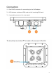
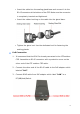
Connectors 1. One RJ-45 connector for connecting to the PoE adaptor. 2. LED indicator inside and SIM card slot for inserting SIM card. 3. A grounding screw on the rear panel.
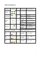
LED Indicators LED Name Location Color LED Behavior Status Indication ON Power On OFF Power Off Steady ON Detect Ethernet Device Connected Blinking N/A OFF No Ethernet action LED list Main Power Ethernet Status SIM status Blue Yellow Green LTE Status LED : Link Status Steady ON SIM Detected Blinking when PUK / PIN Code On-hook OFF No SIM Detected When CPE is power on, each LED indicates each link status LET 1 Red Steady ON LTE 2 Red/ Yellow Steady ON LTE 3 Red/ Yellow/ Steady
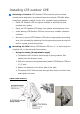
Installing LTE outdoor CPE Selecting a Location: LTE Outdoor CPE should be pole-mounted outdoors and aligned so its antenna faces the nearest LTE eNB. When selecting a suitable location for the unit, consider these guidelines: • Place LTE Outdoor CPE as high as possible to achieve the best possible link quality. • Place the LTE Outdoor CPE away from power and telephone lines. • Avoid placing LTE Outdoor CPE too close to any metallic reflective surfaces.
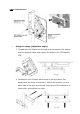
[ With 16dBi antenna ] • Using the clamp [adjustable angle] 1. Thread the M10*20mm bolt through a spring washer, flat washer and the bracket holes, and tighten the bolts to the LTE Outdoor CPE. 2. Thread the M10*100mm bolt through a spring washer, flat washer and the holes of bracket A. Attach the bracket A to the other side of the pole and through both holes of the bracket B on either side, and tighten the bolts.
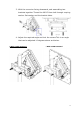
3. With the connector facing downward, and assembling two brackets together. Thread the M10*20mm bolt through a spring washer, flat washer and the bracket holes. 4. Adjust the required angle and lock the screws.This is an angle that can be adjusted 10 degrees above and below.
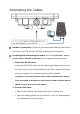
Connecting the Cables Outdoor Connection: Connect a grounding cable between the Ground terminal of the LTE outdoor CPE and a good ground connection. Preparing and connecting the cable: Use only 5E 4x2x24# FTP (or above) outdoor Shielded Patch Cable from an approved manufacturer. 1. Insert the RJ-45 cable: Insert the Cat5 RJ-45 cable into the sealing gland base and connect it to the RJ-45 connector at the bottom of the ODU, labeled. Make sure that the connector is completely inserted and tightened.
• Insert the cable into the sealing gland base and connect it to the RJ-45 connector at the bottom of the CPE. Make sure the connector is completely inserted and tightened. • Insert the rubber bushing on the cable into the gland base. • Tighten the gland nut. Use the dedicated tool for fastening the sealing glands. PoE Connection 1. It is assumed that the RJ-45 is already connected to the LTE outdoor CPE. Assemble an RJ-45 connector with a protective cover on the other end of the LTE outdoor CPE cable. 2.
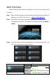
Web Interface Please follow the steps below to configure your device through the web interface: Step1: Open the Web browser (Internet Explorer) and enter the default IP address of the ODU CPE, which is : http://192.168.15.1 Step2: Enter ODU guest login username/password to access the web management interface. The default username/password is admin / admin . Web management interface Step3: The page shown here gets displayed in your browser after login; you can now configure the device settings.
Federal Communication Commission Interference Statement This equipment has been tested and found to comply with the limits for a Class B digital device, pursuant to Part 15 of the FCC Rules. These limits are designed to provide reasonable protection against harmful interference in a residential installation. This equipment generates, uses and can radiate radio frequency energy and, if not installed and used in accordance with the instructions, may cause harmful interference to radio communications.
Professional installation instruction Please be advised that due to the unique function supplied by this product, the device is intended for use with our interactive entertainment software and licensed third-party only. The product will be distributed through controlled distribution channel and installed by trained professional and will not be sold directly to the general public through retail store. 1.