
Install Drawing


© Copyright 2003-2010. Gen-Tran Corporation. All rights reserved. Gen/Tran and PowerStay are registered trademarks of Gen-Tran Corporation. PIB Install Inst. Rev E
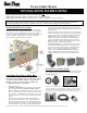
Power Inlet Boxes
INSTALLATION INSTRUCTIONS
Models 53001, 14201, 14301, 63651: Aluminum w/ male locking inlet and a circuit breaker when req’d. SUITABLE FOR USE AS SERVICE EQUIPMENT
Models 53002, 14202, 14302, 63652: Aluminum with male locking inlet
Models 53003, 14203, 14303, 63653: Non-Metallic Nylon resin with male locking inlet
Models 53004, 14204, 14304, 63654: Non-Metallic Nylon resin with male locking inlet and spring-loaded flip lid
Warning: Installation of this Power Inlet Box and related wiring must be done by a qualified electrician in compliance with all applicable electrical
codes. Power Inlet Boxes provided with circuit breakers are designed for locations where the authority having jurisdiction has deemed that a
“permanently installed generator outdoors” is considered to be a separate structure, thus requiring a service entry disconnect.
Proper Installation Location :
Be sure to install this power inlet box in a location that ensures that the
generator is at least 5 feet away from windows, doors or other openings
such as dryer vents, or air conditioning units. Hazardous fumes from
generators are colorless and often odorless, and can enter your home from
a variety of openings. During operation, be sure that your portable
generator exhaust is away from any type of opening.
Installing the Power Inlet Box:
These instructions describe how to install a remotely located
power inlet box for supplying power to a PowerStay
®
Manual
or Automatic Transfer Switch. This box can be painted to
match the exterior color of your house or dwelling. We
recommend painting prior to installation.
1. Remove the front cover.
2. For Models ending in xxxx1, open the front door by removing
the screw(s) near the bottom. For Models ending in xxxx2,
xxxx3, or xxxx4 and for installations where side clearance is less
than 12” on either side, remove the 3 screws that secure the inlet to
the bottom plate. For installations where side clearance exceeds 12”
on both sides, remove the 4 screws that secure the bottom plate to
the box.
3. Mount the power inlet box on the outside of the building in a
convenient location (minimum 24” above grade), using the four
holes provided in the back of the cabinet Sealant should be used
around the anchoring screws to keep water from entering the box at
these mounting holes. Using approved wiring methods, install the
wiring through one of the knockouts provided in the enclosure. Be
sure to seal around the hole in the building where the conduit enters
through the wall.
4. Extend wiring inside the power inlet box approx. 8” from the point of
entrance. Attach green or bare ground wire to green lead provided
in power inlet box with wire nut (provided by installer). On models
WITHOUT circuit breaker, strip and insert incoming leads into
terminals on power inlet. Insert white wire (neutral) into nickel-
plated screw terminal or white marking on the inlet. On models
WITH circuit breaker, attach the incoming hot leads to the wires on
the breaker with wire nuts (provided by installer).
5. For models ending in “1” carefully fold wires into the enclosure
and reattach the dead front cover to the enclosure using the two
screws removed earlier. If circuit breaker is provided, turn circuit
breaker to “ON” position and reinstall front cover with screw
removed earlier. For models ending in xxxx2, xxxx3, or
xxxx4, carefully fold wires into the enclosure and reattach the
bottom assembly or inlet onto box with screws removed earlier.
Accessories you may need:
Optional Flip Lid (sold separately) keeps out dirt and moisture (included in
models ending in XXXX4). Order Part number FLPIB. (See other side for
installation instructions)
If you need a transfer switch, power cord or plugs and connectors to complete your
generator installation, let us know. Male plugs connect to generator, and female
receptacles connect to Power Inlet Box or Transfer Switch. Check your generator
receptacle for exact receptacle configuration to avoid ordering the wrong part.