
User's Manual

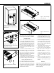

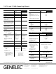

Figure 15. The upper curve group shows the horizontal directivity
characteristics of the 1237A in its vertical configuration measured at
2 m. The lower curve is a 1/6 octave smoothed power response.
Figure 16. The upper curve group shows the horizontal directivity
characteristics of the 1238A in its vertical configuration measured at
2 m. The lower curve is a 1/6 octave smoothed power response.
vide reasonable protection against harmful
interference in a residential installation. This
equipment generates, uses and can radiate
radio frequency energy and, if not installed
and used in accordance with the instruc-
tions, may cause harmful interference to
radio communications. However, there is no
guarantee that interference will not occur in a
particular installation. If this equipment does
cause harmful interference to radio or televi-
sion reception, which can be determined by
turning the equipment off and on, the user is
encouraged to try to correct the interference
by one or more of the following measures:
1. Reorient or relocate the receiving
antenna.
2. Increase the separation between the
equipment and receiver.
3. Connect the equipment into an outlet on
20
20k
50
100
200
500
1k 2k
5k
10k
Hz
Genelec Oy 1237A (dBr) vs freq (Hz) 31 Mar 14
0°
60°
15°
30° 45°
50
55
60
65
70
75
80
85
90
95
d
B
r
A
20
20k
50
100
200
500
1k 2k
5k
10k
Hz
Genelec Oy 1238A (dBr) vs freq (Hz) 31 Mar 14
0°
60°
15°
30° 45°
50
55
60
65
70
75
80
85
90
95
d
B
r
A
Figure 17. 1237A horizontal directivity plot. Figure 18. 1238A horizontal directivity plot.
a circuit different from that to which the
receiver is connected.
4. Consult the dealer or an experienced
radio/TV technician for help.
Modifications not expressly approved by the
manufacturer could void the user’s authority
to operate the equipment under FCC rules.
Figure 19. 1237A vertical directivity plot. Figure 20. 1238A vertical directivity plot.