
User's Manual


“DIGITAL THRU AES/EBU” Connector
This output carries an unaltered copy of
the digital audio signal and can be used for
daisy-chaining the signal up to three addi-
tional SAM monitors or subwoofers.
“ANALOG IN” Connector
The maximum input level of the analog input
is +25.0 dBu. The analog input must not be
overloaded, otherwise distortion will result.
When the maximum input is exceeded, the
enclosure front panel light turns red, indicat-
ing the overload.
The sensitivity of the monitor system is
set using the GLM software. Coming from
the factory, the analog input is set to the
highest sensitivity, resulting in a sound
output of 100 dB SPL for a -6 dBu analog
input signal.
“CONTROL NETWORK” Connectors
The RJ-45 sockets connect the monitor to
the proprietary Genelec Loudspeaker Man-
ager™ (GLM™) network. Do not connect to
Ethernet LAN.
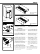
“Loudspeaker Connectors” Group
These connectors are used when the RAM-L
amplifier is mounted separately in an equip-
ment rack.
1. “LED” Connector
This RJ-45 socket is a connection for
the front panel warning LED.
2. “Woofer” Connector
A standard four-pole Speakon cable
connects to the woofer.
3. Midrange/Tweeter” Connector
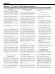
Figure 3. GLM network cabling
LISTENING
POSITION
MICROPHONE
GLM
NETWORK
GLM
NETWORK
GLM
NETWORK
USB
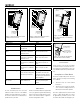
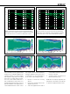
Figure 1. The location of the acoustic axis.
H1 mm (in) W1 mm (in) H2 mm (in) W2 mm (in)
1237A 540 (21
1
/4 in) 200 (7
7
/8 in) 230 (9
1
/16 in) 170 (6
11
/16 in)
1238A 650 (25
5
/8 in) 240 (9
1
/2 in) 282 (11
1
/8 in) 202 (7
15
/16 in)
both A and B subchannels are reproduced by
the monitor. GLM software is used to set up
the monitor to specific channel assignments.
RAM-L Amplifier
Power Button
The power button in the middle of the RAM-L
amplifier front panel controls several functions.
A short press of the power button turns
RAM-L on or off. Turning on, the power button
light flashes rapidly, and lights on steadily
when the turn-on has been completed.
Testing modes are explained later in this
manual.
Setting ISS™
The Intelligent Signal Sensing (ISS) puts the
monitor to a power-saving stand-by mode
automatically. The factory setting for ISS is
"OFF." The ISS can be activated using the
GLM software (see Figure 5). When ISS is
active, if no audio signal is sensed during
the selected time, the monitor powers down.
The monitor will power up again once a
signal is detected. The ISS setting is applied
to all ISS-enabled monitors in the currently
selected Setup.
Connections
“MAINS INPUT” Connector
Connect to the mains supply.
“DIGITAL IN AES/EBU” Connector
The monitor defaults to reproducing an
analog input signal. The digital audio AES/
EBU input is selected automatically when a
valid digital audio signal is presented. Use
GLM software to define the AES/EBU sub-
frame to monitor.
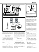
L
R
C
30
0
RS
LS
100 120
0- 0
Figure 2. Recommended placement and
alignment of monitors in a 5-channel
system (ITU-R BS.775-1)