
User's Manual


A standard four-pole Speakon cable
connects to the the midrange and
tweeter.
Front Panel Light Functions
Green light on the DCW panel of a 1237A
or 1238A enclosure indicates normal opera-
tion. A yellow light indicates certain activities
when the GLM control software is used. The
light turns red in an overload condition. The
overload light (red) is activated by several
events:
1. Exceeding the maximum input of the
analog input
2. Reaching close to the digital input maxi-
mum (high likelihood of digital clipping)
3. Overload of drivers or amplifier, or clip-
ping in the power amplifier
4. An error detected in the AES/EBU audio
data
If a red warning light appears on the moni-
tor enclosure, turn the source level down.
Ensure that there are no bit errors in the
AES/EBU digital audio data transmission.
Mounting RAM-L Amplifier
in a 19 Inch Rack
The RAM-L amplifier can be removed from
the enclosure and installed in a standard 19
inch rack. The rack mount components (front
plate, brackets, screws) are included with the
monitor.
Preparation for rack mount is done with the
following process:
1. Remove all signal cables and the mains
cable from the amplifier.
2. Remove the two screws attaching
the amplifier to the vibration isolating
mounts at the left top and bottom.
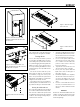
3. Pull out the left side of the amplifier (see
figure 6).
4. Detach the flat cable from the enclosure.
5. Undo the two screws on the right side
isolating mounts. Remove the amplifier.
6. Remove the cover of the flat cable con-
nector (see figure 7)
7. Pull out (detach) the flat cable from the
amplifier unit.
8. Reattach the cover of the flat cable con-
nector.
9. Remove the front mounting ears (see
figure 8).
10. Attach two angled rack mount brack-
ets (included). Attach the front plate
(included) (see figures 9 and 10).
11. Attach the amplifier to a 19 inch rack.
12. Remove the plastic cover from the RJ45
connector. Attach two Speakon cables,
and one RJ45 cable (LED CONNECTOR)
between the amplifier and the cabinet.
13. Attach signal cables and the mains cable.
Flush Mounting the
Monitor Enclosure
Flush mounting offers acoustical benefits.
No cabinet edge diffraction will occur. Low
frequency reflections from the wall behind
the monitor can be avoided. The monitor’s
acoustical axis (Figure 1) should point to the
seated listening position. The wall in which
the monitors are mounted should be stiff and
heavy. The monitors should not be mounted
too high (maximum tilt angle < 15 degrees).
A space 50 to 100 mm (2 to 4”) wide can
be left around the monitor but this space
should be covered with a panel in the front.
Leave a gap of 5 to 10 mm (¼ to ½”) between
the monitor and the panel. Fill this gap with a
soft rubber gasket (see figure 14). The moni-
tor should be mounted on vibration isolators.
The resonant frequency of movement for the
mounted monitor should be between 2 to 8 Hz.
An empty cavity in the wall should be filled
with absorbent mineral wool or foam plas-
tic. A wooden wall structure must be heavily
braced (see figure 11). In a solid (e.g. con-
crete) wall structure, the space around the
cabinet should be filled with absorbent min-
eral wool or sand bags (see Figure 12).
Ensure that the cabinet is flush with the
surface of the wall. If a decorative cloth frame
is used the edges adjacent to the monitors
must be less than 20 mm (3/4 in) deep.
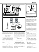
Figure 4. Connector panel of the RAM-L amplifier.
LED CONNECTOR
CONNECT ONLYTO GENELEC NETWORK.
ANALOG
IN
DIGITALIN
AES/EBU
DIGITALTHRU
AES/EBU
MAINS INPUT
50 /60Hz 750 W
100 - 230 V~
SERIAL NUMBER
MIDRANGE /
TWEETER
WOOFER
LOUDSPEAKER CONNECTORS
RAM-L AMPLIFIER
MODULE
www.genelec.com
MADE IN FINLAND
CONTROL NETWORK
213
THRU
IN
1
1
23
3
2
-
GND
+
DIRECT
LOUDSPEAKER
CONNECTOR
CONSULT OPERATING
MANUAL BEFORE
OPENING !
ANALOG
AUDIO
INPUT
DIGITAL
AUDIO
INPUT
DIGITAL
THRU
CONNECTOR
CONTROL
NETWORK
CONNECTORS
LOUDSPEAKER CONNECTORS
(ONLY USED WHEN THE AMPLIFIER IS
MOUNTED SEPARATELYINARACK)
MAINS
CONNECTOR
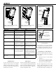
Figure 5. Selecting ISS setting.
Cable gauge Max. length
2,0 mm
2
(14 AWG) 30 m (100 ft)
3,3 mm
2
(12 AWG) 40 m (130 ft)
5,3 mm
2
(10 AWG) 60 m (200 ft)
Table 1. Recommended cable thicknesses
for different lengths of signal cable