7040A Operating Manual Genelec 7040A Active Subwoofer
Genelec 7040A Active Subwoofer Introduction Driver Congratulation and thank you for choosing Genelec! Since 1978, Genelec has been guided by a single idea – to make perfect active monitors that deliver neutral and accurate sound in every kind of acoustical environment. In Genelec’s quest for this ultimate goal, our unrivalled commitment to research and development has led us to continuously develop innovative driver technology, electronic circuitry, enclosure designs and many more.
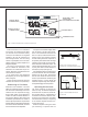
www.genelec.com MADE IN FINLAND 7040A ACTIVE SUBWOOFER SIGNAL INPUT CONNECTORS SERIAL NUMBER MAGNETICALLY SHIELDED ROLL-OFF +3 0 -3 -4 +6 +12 LEFT IN RIGHT IN SIGNAL OUTPUT CONNECTORS LEFT OUT RIGHT OUT -4 dB -2 dB BASS ROLL-OFF PHASE AND ISS DISABLE SWITCHES -270° -90° -180° ISS-DISABLE ON -6 dBu POWER SENSITIVITY FOR 100 dB SPL @ 1m MAINS INPUT MAINS INPUT 50 / 60 Hz 70 W 100 - 240 V~ POWER SWITCH Figure 1. 7040A's amplifier panel, connectors and controls.
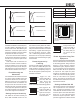
Phase Difference: 90° Phase Difference: 0° Subwoofer placement Bass Roll-Off setting Near to a wall -2 dB In a corner -6 dB Flush mounted -2 dB Table 1. Suggested Bass Roll-Off settings 85 Hz 85 Hz Phase Difference: 270° Phase Difference: 180° 85 Hz 85 Hz Figure 4. The effect of phase difference between the subwoofer and the main loudspeakers subwoofer is installed in a restricted space, such as a cabinet or integrated into a wall structure. See section “Flush Mounting the Subwoofer.
Genelec 7040A subwoofer has been designed in accordance with international safety standards. However, to ensure safe operation and maintain the unit in safe operating condition, the following warnings and cautions must be observed: • • • • • • Do not expose the subwoofer to water or moisture. Do not place any objects filled with liquid, such as vases on the subwoofer or near it. Servicing and adjustment must only be performed by authorized Genelec service personnel.
7040A Operating Manual SYSTEM SPECIFICATIONS AMPLIFIER SECTION 7040A 7040A Free field frequency response (-6 dB) 30...90 Hz ± 3 dB (33...85 Hz) Amplifier short term output power (Long term output power is limited by driver unit protection circuitry) 50 W Accuracy of frequency response Maximum short term sine wave SPL output averaged from 40 to 85 Hz, measured in half space at 1 meter 100 dB Amplifier system THD at nominal output ≤ 0.