
User Manual


subwoofer is installed in a restricted space,
such as a cabinet or integrated into a wall
structure. See section “Flush Mounting the
Subwoofer.” A restricted space must be
suciently ventilated to prevent ambient
temperature rise above 35 °C (95 °F).
Do not cover the driver of the subwoofer.
Do not place the subwoofer so that there is
less than 10 cm (4 in) of free space in front
of the grille.
Thick carpets under the subwoofer can
block the ventilation clearance needed for
cooling the amplier unit. To ensure proper
functioning of the reex port the reex port
side (opposite of the connector panel) should
have a minimum clearance of 7.5 cm (3 in).
Flush Mounting the
Subwoofer
If the subwoofer is ush mounted into a wall
or a cabinet, ensure amplier cooling and
unrestricted airflow from the reflex port.
Make the recess 7.5 cm (3 in) wider than
the subwoofer. Place the subwoofer into
the right end of the recess with the driver
side facing the room. This leaves sucient
7.5 cm (3 in) of free space for the reex port.
The height and depth of the recess should
not be much larger than the subwoofer.
Setting the Input Sensitivity
The 7040A has the same sensitivity as
8010, 8020 and M030 monitors in free
eld. However, when placed near reect-
ing surfaces the sensitivity of 7040A typi-
cally must be attenuated due to increased
wall loading. A typical initial setting for
the rotary sensitivity control is -4 dBu.
The +12 dBu setting provides maximum
attenuation The use of proper measuring
equipment with careful listening is highly
recommended.
Phase Alignment by
Listening
Connect an audio frequency signal gener-
ator to LEFT IN or RIGHT IN input of the
7040A and feed in an 85 Hz tone. Connect
a monitor to the corresponding output, so
that the test signal is reproduced by both
subwoofer and monitor.
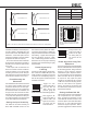
Toggle the -180°
phase switch (DIP 4
from left) "ON" and
"OFF". Set it to the
position giving the
lowest sound level at the listening position.
Next, toggle the -90°
phase switch (DIP 3)
"ON" and "OFF", and
again set it to the posi-
tion which gives the
lowest sound level.
Finally, invert the -180°
phase switch (DIP 4)
position to the oppo-
site setting. Now you
can remove the test
signal.
Phase Alignment Using Test
Equipment
Feed in the test signal to LEFT IN or RIGHT
IN of the subwoofer. Place the microphone
at the listening position. Using a real-time
analyser or other frequency response
measurement system, adjust the sensitiv-
ity of the subwoofer until the frequencies
below and above 85 Hz are reproduced
at equal level. Then, adjust the phase
switches for the maximum dip of at least
-6 dB at the crossover frequency (85 Hz).
Invert the -180° switch to the opposite
setting. The phase is now aligned and
the measurement should show a smooth
response around 85 Hz.
Setting the Bass Roll-Off
The acoustic response of the subwoofer
can compensate the room character-
istics. To adjust the subwoofer use the
''Bass Roll-O' switches located on the
connector panel. These oer attenuation
levels of -2, -4, and -6 dB at the lowest
subwoofer output frequencies. Table 1
provides suggestions for Bass Roll-Off
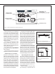
Figure 4. The effect of phase difference between the subwoofer and the main loudspeakers
Phase Difference: 0°
85 Hz
Phase Difference: 180°
85 Hz
Phase Difference: 270°
85 Hz
Phase Difference: 90°
85 Hz
Figure 5. Flush mounting the subwoofer.
Note the clearance needed on the reflex
port side.
Table 1. Suggested Bass Roll-Off settings
Subwoofer placement Bass Roll-Off
setting
Near to a wall -2 dB
In a corner -6 dB
Flush mounted -2 dB
ON
OFF
ON
OFF
ON
OFF