
User Manual


clearance of at least 7.5 centimeters (3") to
any objects to ensure proper functioning of
the reex port.
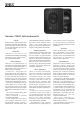
Flush Mounting The
Subwoofer
If the subwoofer is flush mounted into a
wall or a cabinet, it is important to ensure
amplifier cooling and unrestricted airflow
from the reex port. This can be done by
making the recess 7.5 centimeters (3") wider
than the subwoofer. Place the subwoofer
into the right end of the recess with the
driver side facing the room. This leaves
sucient 7.5 centimeters (3") of free space
on the reex port side. The height and depth
of the recess should not be any bigger than
is needed to t the subwoofer ush with the
wall surface.
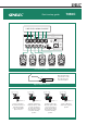
Sensitivity Adjustment
The subwoofer requires input sensitivity
alignment to the source to obtain a
correctly balanced system. The input
sensitivity control is located on the
connector panel of the subwoofer. An
input voltage of -6 dBu with a -6 dBu input
sensitivity setting will produce 100 dB SPL
@ 1 m in free eld.
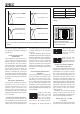
Setting The Phase Control
Incorrect phase alignment between the
main loudspeakers and subwoofer causes
a drop in the frequency response of the
whole system at the crossover frequency.
The graphs above (Fig. 5) show the eect
of phase difference to the frequency
response.
The phase dierence between the main
loudspeakers and subwoofer at the listening
position is dependent upon the position of
the subwoofer, so the phase adjustment
should be done only after the preferred
position is found. Acoustic measuring
equipment is required for accurate system
alignment. If this equipment is not available,
the following coarse phase matching can
be applied.
Coarse Phase Adjustment
Method
Connect an audio frequency signal generator
to one of the inputs of the 7050C and set
it to feed a 85 Hz signal to the system.
Alternatively, you can use a 85 Hz signal
fom a suitable audio test recording. Make
sure you connect (even temporarily) a main
loudspeaker to the corresponding output
on the subwoofer, so that the test signal is
properly reproduced by both subwoofer and
main loudspeaker.
Toggle the -180° phase
switch (DIP 4 from left)
"ON" and "OFF", and
set it to the position
which gives the lowest
sound level at the listening position.
Next toggle the -90° phase switch (DIP 3)
"ON" and "OFF", and
again set it to the position
which gives the lowest
sound level.
Finally, set the -180°
phase switch (DIP 4) to
the opposite setting and
deactivate the test signal.
Phase Correction Method
With Test Equipment
The following procedure matches the phase
between the subwoofer and the main
loudspeakers using a frequency analyser
and a pink noise generator. Connect a
high grade measuring microphone to the
analyser and feed pink noise into one of
the inputs of the subwoofer. Position the
microphone at the listening position and
adjust the input sensitivity of the subwoofer
until frequencies below and above 85 Hz are
reproduced at equal level. Then adjust the
phase control switches for the maximum
dip of at least -6 dB at the crossover
frequency (85 Hz).
Change the -180° switch to the opposite
setting. The phase should now be set
correctly and the frequency analyser should
show a smooth response around 85 Hz.
Using The LFE +10 dB
Function
The LFE channel is usually recorded 10 dB
lower than the main channels so that there
Figure 5. The eect of phase dierence between the subwoofer and the main loud-
speakers
Phase Difference: 0°
85 Hz
Phase Difference: 180°
85 Hz
Phase Difference: 270°
85 Hz
Phase Difference: 90°
85 Hz
Figure 6. Flush mounting the
subwoofer. Note the clearance needed
on the reex port side.
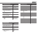
Table 1. Suggested Bass Roll-O
settings
Subwoofer placement Bass Roll-Off
setting
Near to a wall -4 dB
In a corner -8 dB
Flush mounted -4 dB
4321 765