LSE Series Gen 7060A+7070A+7071A 1 Prosessimusta Operating Manual Genelec 7060A, 7070A and 7071A Active Subwoofers 22.5.
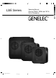
7060A, 7070A and 7071A Active Subwoofers General description Genelec 7060A, 7070A and 7071A are pow- easy subwoofer level matching with various Before connecting the audio signals, ensure main speakers. All outputs have 0 dB pass- that both the subwoofer and the main moni- band gain. tors are switched off.
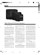
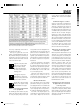
Figure 2. XLR to RCA connector for unbalanced operation. Figure 1. 7070A's amplifier panel, connectors and controls. Figure 3. Recommended distances to the front wall Pro Logic) should not be connected to the way as with the Front channels. Also these offset from the center of the front wall. "LFE IN" input. See section "Subwoofer in channels are high pass filtered at 85 Hz. The recommended distance to the wall is analogue matrix sound systems".
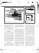
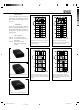
Phase Difference: 90° Phase Difference: 0° 85 Hz Table 1. Suggested Bass Roll-Off settings 85 Hz Phase Difference: 270° Phase Difference: 180° 85 Hz 85 Hz Figure 4. The effect of phase difference between the subwoofer and the main monitors Figure 5. Flush mounting the subwoofer. Note the clearance needed on the reflex port side. Although the 7060A, 7070A and 7071A fier cooling. This can be done by making the panel.
consists of a LED in a compact case and a RJ11 cable to connect the case and the "REMOTE" RJ11 connector on the amplifier panel. Subwoofer bypass control A bypass control feature is included in the subwoofer circuits so that the effect of the subwoofer on the whole monitor system can be determined. With the bypass switch on, the high pass filters for the main monitors are overridden and the system behaves as if the subwoofer was not connected. The bypass function has no effect on the LFE input.
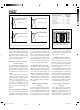
Using the LFE +10 dB function subwoofers 12 dB compared to a single and 7071A can be set to two frequency In Dolby Digital and DTS encoding formats subwoofer. Adjust the sensitivity control of all ranges: 19 to 85 Hz or 19 to 120 Hz by the LFE channel has to be monitored with subwoofers in the group to match the SPL using the "LFE BANDWIDTH" switch. If the +10 dB gain in relation to the main channels. level of the main monitor system.
Maintenance No user serviceable parts are inside the amplifier unit. Any maintenance of the unit must only be performed by qualified service personnel. Guarantee This product is supplied with a ONE year guarantee against manufacturing faults or defects that might affect the performance of the unit. Refer to supplier for full sales and guarantee terms.
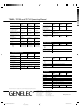
7060A, 7070A and 7071A Operating Manual SYSTEM SPECIFICATIONS Free field frequency response (+/- 3 dB) Maximum short term sine wave SPL output averaged from 30 to 85 Hz, measured in half space at 1 meter AMPLIFIER SECTION 7060A 7070A 7071A 29 Hz…85 Hz LFE 85/120 Hz 19 Hz…85 Hz LFE 85/120 Hz 19 Hz…85 Hz LFE 85/120 Hz ≥ 108 dB SPL Maximum peak SPL output with random pink noise, measured in half space at 1 meter ≥ 113 dB SPL Self generated noise level in free field @ 1 m on axis (A-weighted) ≤ 15