
User Manual

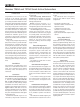
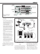

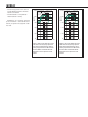


Figure 1. Connector panel
of the 7360A. The 7370A
is similar.
Figure 2. GLM Network cabling. Audio cabling not shown.
MICROPHONE
PLACED IN
THE LISTENING
POSITION
292-0063
GLM
TERMINATOR
COMPUTER
RUNNING
GLMSOFTWARE
USB CABLE
GLM ADAPTER
GLM NETWORK
CABLE
MONITORS
SUBWOOFER
The setup is fast and consists of the
following steps:
• Connect a CAT5 (RJ45) cable between
each monitor (and subwoofer) and nally
to the control network input of the GLM
Adapter device (see Figure 1).
• Connect the GLM Adapter device to
computer USB connector.
• Using a microphone stand, place the
Genelec measurement microphone at the
listening location with the microphone
pointing upwards and the microphone
top at the height of the engineer’s ear.
The microphone is a part of the GLM
User Kit.
• Connect the microphone cable to the
microphone input in the GLM Adapter
device.
• Download the GLM software at the
Genelec web site (www.genelec.com).
• Install the GLM software and follow the
instructions in the software to measure
and set up your system.
• If you plan to not use a computer for
controlling the monitors, use the GLM
software to write the setting into the
monitors (use menu item “Store | Store
the Current Group Settings…”).
While the GLM network is disconnected
the settings stored using the Genelec
Loudspeaker Manager software can be
selected in use by setting the STORED
switch ON.
Using Without GLM
Cabling
The 7300 series subwoofers can be easily set
up using the xed 85 Hz analogue crossover
filter. This fixed crossover filter is on as
a factory setting and highpass filters the
analogue outputs on the subwoofer. When
using this method, run each signal cable rst
to the subwoofer. Then, run the respective
output to the monitor. This monitor feed
signal is highpass ltered at 85 Hz.
When using the LFE signal, run the LFE
signal to the subwoofer LFE in connector.
When daisy-chaining multiple
subwoofers, run a cable from the Link Out
connector the next subwoofer’s Link In
IN 3IN4
OUT 3 OUT 4
IN 5
OUT 5
IN 6IN7
OUT 6 OUT 7
LFE IN
LFE OUT
LINK OUT
LINK IN
OUT 2
IN 1IN2
OUT 1
TEST 1
TEST 2
GLM NETWORK
ANALOGANALOGANALOG
SERIAL
NUMBER
RESET TO FACTORY
SETTINGS: PUSH
BUTTON FOR 10 SEC
MAINS INPUT
50 /60Hz300 W
100-240 V~
-4
0
+2
-2
-6
+4 +12
+8
PHASE
LFE +10 dB
STORED
ISS
TEST TONE
A/B
DIGITALLFE
-20dB
-10dB
LEVEL
BASS ROLL-OFF
BYPASS
ON/OFF
LFE CHANNEL
7360A SMART ACTIVE SUBWOOFER
WARNING
ELECTRIC SHOCK HAZARD. DO
NOT OPEN. DO NOT SUBJECT
TO WATER OR MOISTURE. NO
USER SERVICEABLE PARTS
INSIDE. REFER SERVICING TO
QUALIFIED PERSONNEL. USE
EARTHED MAINS CONNECTION
ONLY.
THIS DEVICE COMPLIES
WITH FCCPART15 AND
CANADIAN ICES-003 RADIO
FREQUENCY CLASSBEMISSION
REQUIREMENTS. REFER TO
OPERATING MANUAL FORFULL
INFORMATION.
LAITE ON LIITETTÄVÄ SUOJAKOSKETTIMILLA
VARUSTETTUUN PISTORASIAAN.
APPARATETMÅ TILKOPLES JORDET STIKKONTAKT.
APPARATENSKALL ANSLUTAS TILL JORDAT UTTAG.
RISQUEDE CHOC ÉLECTRIQUE.NE PA S OUVRIR. NEPA S
EXPOSERÀL'EAU OU L'HUMIDITÉ.AUCUN COMPOSANTÀ
L'INTÉRIEUR REMPLAÇABLE PARL'UTILISATEUR.ADRESSER
TOUTE RÉPARATIONÀUN PERSONNELQUALIFIÉ.
CET APPAREIL DOIT ÊTRE RACCORDÉÀLA TERRE.
AVERTISSEMENT
MADE IN FINLAND
www.genelec.com
ON OFF
-90°
-180°
-4 dB
-8 dB
INPUT dBu
100 dB SPL (1 m)
PRODUCING
DIGITAL
OUT
IN
AES/EBU IN/OUT
CONNECTORS
GLM NETWORK
CONNECTORS
ANALOG
IN/OUT
CONNECTORS
POWER
SWITCH
MAINS
INPUT
ROTARY
LEVEL
ADJUSTMENT
CONTROL
SWITCHES
BYPASS
SWITCH
CONNECTOR