
User Manual-7050B


a drop in the frequency response of the
whole system at the crossover frequency.
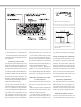
The graphs above (Fig. 4) show the effect of
phase difference to the frequency response.
The phase difference between the main
loudspeakers and subwoofer at the listen-
ing position is dependent upon the position
of the subwoofer, so the phase adjustment
should be done only after the preferred posi-
tion is found. Acoustic measuring equipment
is required for accurate system alignment. If
this equipment is not available, the following
coarse phase matching can be applied.
Coarse phase adjustment
method
Connect an audio frequency signal generator
to the “FRONT CENTER” input of the 7050B
and set it to feed a 85 Hz signal to the system.
Alternatively, you can use a 85 Hz signal fom
a suitable audio test recording. Make sure
you connect (even temporarily) a main loud-
speaker to the "FRONT CENTER" output, so
that the test signal is properly reproduced by
both subwoofer and main loudspeaker.
Toggle the -180° phase
switch (DIP 5 from left)
"ON" and "OFF", and set it
to the position which gives the lowest sound
level at the listening position.
Next toggle the -90° phase
switch (DIP 4) "ON" and
"OFF", and again set it to
the position which gives
the lowest sound level.
Finally, set the -180° phase
switch (DIP 5) to the oppo-
site setting and deactivate
the test signal.
Phase correction method with
test equipment
The following procedure matches the phase
between the subwoofer and the main loud-
speakers using a frequency analyser and a
pink noise generator. Connect a high grade
measuring microphone to the analyser and
feed pink noise into the "CENTER IN" input of
the subwoofer. Position the microphone at the
listening position and adjust the input sensi-
tivity of the subwoofer until frequencies below
and above 85 Hz are reproduced at equal
level. Then adjust the phase control switches
for the maximum dip of at least -6 dB at the
crossover frequency (85 Hz).
Change the -180° switch to the opposite
setting. The phase should now be set cor-
rectly and the frequency analyser should
show a smooth response around 85 Hz.
Using the LFE Bandwidth and
LFE +10 dB functions
The “LFE BANDWIDTH” switch allows you to
select the upper cutoff frequency of the LFE
channel between 85 and 120 Hz. Limiting the
LFE bandwidth to 85 Hz can be used to simu-
late the effect of some consumer decoders
that do not replay information above 80 Hz on
the LFE channel when the bass management
is used. Checking the multichannel mix with
this setting on lets you know how it translates
in systems with this limitation.
The 120 Hz LFE bandwidth setting com-
plies with the replay systems of movie theat-
ers and cinemas. 35 mm movie soundtracks
use the LFE channel to reproduce a band-
width of 20 - 120 Hz through dedicated
subwoofers. In this case the LFE and main
channel bandwidths overlap between 85 and
120 Hz, which may create unwanted acousti-
cal summing if the same signal is present in
both channels. To avoid this, the LFE content
should be kept completely different (de-cor-
related) from the low frequency content of
Figure 4. The effect of phase difference between the subwoofer and the main loudspeakers
Phase Difference: 0°
85 Hz
Phase Difference: 180°
85 Hz
Phase Difference: 270°
85 Hz
Phase Difference: 90°
85 Hz
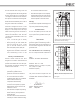
Figure 5. Flush mounting the subwoofer.
Note the clearance needed on the reflex
port side.
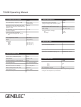
Table 1. Suggested Bass Roll-Off settings
Subwoofer placement
Bass Roll-Off
setting
Near to a wall
-2 dB
In a corner
-6 dB
Flush mounted
-2 dB