
User's Manual


5
Guarantee
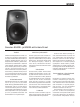
Genelec 8040B and 8050B are supplied with
two year guarantee against manufacturing
faults or defects that might alter the perfor-
mance of the loudspeakers. Refer to supplier
for full sales and guarantee terms.
Compliance to FCC rules
This device complies with part 15 of the FCC
Rules. Operation is subject to the following
two conditions:
• This device may not cause harmful
interference
• This device must accept any
interference received, including
interference that may cause undesired
operation.
20
20k
50
100
200
500
1k 2k
5k
10k
Hz
Genelec Oy 8040 horizontal off axis response level (dBr) vs freq (Hz) 6 Apr 04
0°
60°
15°
30°
45°
50
100
55
60
65
70
75
80
85
90
95
d
B
r
A
100
90
95
20
20k
50
100
200
500
1k 2k
5k
10k
Hz
Genelec Oy 8040 (dBr) vs freq (Hz) 6 Apr 04
80
85
90
d
B
r
A
DESKTOP LF
BASS TILT
BASS ROLL-OFF
TREBLE TILT
80
85
90
80
85
90
20
20k
50
100
200
500
1k 2k
5k
10k
Hz
Genelec Oy 8050 (dBr) vs freq (Hz) 6 Apr 04
0°
60°
15°
30°
45°
50
100
55
60
65
70
75
80
85
90
95
d
B
r
A
100
90
95
20
20k
50
100
200
500
1k 2k
5k
10k
Hz
Genelec Oy 8050 (dBr) vs freq (Hz) 6 Apr 04
80
85
90
d
B
r
A
BASS ROLL-OFF
TREBLE TILT
80
85
90
80
85
90
DESKTOP LF
BASS TILT
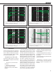
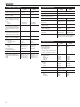
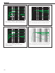
Figure 7. The curves above show the effect of the “bass tilt”,
“treble tilt”, “desktop low frequency” and “bass roll-off” controls
on the free field response of the 8040B.
Figure 8. The upper curve group shows the horizontal directivity
characteristics of the 8040B measured at 1 m. The lower curve shows
the system's power response.
Figure 9. The curves above show the effect of the “bass tilt”,
“treble tilt”, “desktop low frequency” and “bass roll-off” controls
on the free field response of the 8050B
Figure 10. The upper curve group shows the horizontal directivity
characteristics of the 8050B measured at 1 m. The lower curve shows
the system's power response.
Note: This equipment has been tested and
found to comply with the limits for a Class
B digital device, pursuant to part 15 of the
FCC Rules. These limits are designed to pro-
vide reasonable protection against harmful
interference in a residential installation. This
equipment generates, uses and can radiate
radio frequency energy and, if not installed
and used in accordance with the instruc-
tions, may cause harmful interference to
radio communications. However, there is no
guarantee that interference will not occur in a
particular installation. If this equipment does
cause harmful interference to radio or televi-
sion reception, which can be determined by
turning the equipment o and on, the user is
encouraged to try to correct the interference
by one or more of the following measures:
1. Reorient or relocate the receiving antenna.
Increase the separation between the equip-
ment and receiver.
2. Connect the equipment into an outlet on a
circuit dierent from that to which the receiver
is connected.
3. Consult the dealer or an experienced radio/
TV technician for help
Modifications not expressly approved
by the manufacturer could void the user’s
authority to operate the equipment under
FCC rules.