
Manual
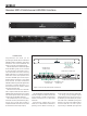

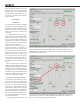
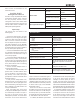
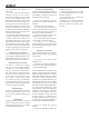


Figure 2. Audio and GLM
network cabling for an 8.0
channel system. In this
conguration the 9301A routes
the sum of all eight channel
inputs to the subwoofer.
GLM NETWORK
GLM ADAPTER
AES IN 1
DIGITAL
OUT
DIGITAL
IN
DIGITAL
IN
AES IN 2 AES IN 3 AES IN 4 (LFE)
8.0 CHANNEL AUDIO SOURCE
AES OUT 1 AES OUT 2 AES OUT 3 AES OUT 4
SUBWOOFER
LINK
= AES/EBU DIGITAL CABLING
=GLM NETWORK CABLING
POSSIBLE
DAISY-CHAINED
ADDITIONAL
SUBWOOFERS
GLM NETWORK
GLM ADAPTER
AES IN 1
DIGITAL
OUT
DIGITAL
IN
DIGITAL
IN
AES IN 2 AES IN 3 AES IN 4 (LFE)
7.1 CHANNEL AUDIO SOURCE
AES OUT 1 AES OUT 2 AES OUT 3 AES OUT 4
SUBWOOFER
LINK
= AES/EBU DIGITAL CABLING
=GLM NETWORK CABLING
POSSIBLE
DAISY-CHAINED
ADDITIONAL
SUBWOOFERS
AES IN 1 AES IN 2 AES IN 3 AES IN4(LFE)
7.1.4 CHANNEL AUDIO SOURCE
GLM ADAPTER
AES IN 1 AES IN 2 AES IN 3 AES IN4(LFE)
AES/EBU DIGITAL
CABLING
GLM NETWORK CABLING
7.1
4
Figure 3. Audio and GLM
network cabling for a 7.1
channel system. In this
conguration the 9301A
routes the sum of all eight
channel inputs and the
LFE channel content to the
subwoofer.
Figure 4. Audio and GLM network cabling for a 7.1.4 channel system. Even larger systems can be congured by using multiple
9301As.