
Manual


9301A controls are embedded into the
subwoofer controls.
Use With GLM™
Management Network
The 9301A is fully compatible with Genelec
Loudspeaker Manager GLM™ software
and the proprietary Genelec monitor
management network and Genelec SAM
monitors. More information about the use
with the GLM™ network is available in the
SAM System Operating Manual.
System setup
The setup is easy and consists of the
following steps:
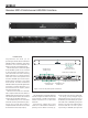
• Connect the digital audio to the input
connectors. If you are using the LFE signal,
connect the cable carrying the LFE to AES/
EBU 4 connector. Continue with cables
from the respective outputs to the monitors.
Use cables intended for carrying AES/EBU
digital audio. Genelec discourages the use
of standard analogue microphone cables as
this may reduce system performance.
• Connect the SUBWOOFER LINK output
to a subwoofer’s DIGITAL IN connector. This
creates a link for the subwoofer to input a
sum of all input signals.
• Connect CAT5 (RJ45) cables between the
9301A and every monitor and subwoofer.
Finally connect to the management network
input of a GLM Adapter device (see Figure 2
and 3). Notice that the order of connecting
devices is not signicant.
• Connect the GLM Adapter device to
computer USB connector.
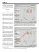
You will nd all your devices initially in the
product stack of the GLM software. When
you find the 9301A in the product stack,
drag and drop it to an area on the Layout
grid adjacent to where the subwoofer will be
placed (see Figure 5).
In case you have multiple 9301A units,
observe that when you click with the mouse
on a 9301A icon, the front panel light on this
9301A starts ashing, indicating the 9301A
that is selected in the GLM software. This
can help in identication.
When "Input Signal Type" of the Group
is changed to AES/EBU Digital, all 9301As
are automatically activated to be part of
the group. At the same time the "AES/
EBU Digital Input Mode" of all 7300 series
subwoofers are turned to Multichannel
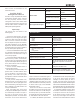
Indicator, colour Colour, indication Indication
Power switch
Solid green
Power on, normal state and
operation
Blinking green GLM is adjusting the 9301A
Green blink every 10 seconds
The 9301A is in ISS power
saving state
No light Power o
Input signal indicator light
Solid green
Valid AES/EBU signal
detected, receiving
No light No input detected
Table 1. Front panel indicator light functions
SPECIFICATIONS
Weight 2 kg (4.4 lbs)
Dimensions:
Height
Width
Depth
44 mm (1 11/16 in)
466 mm (18 3/8 in)
211 mm (8 5/16 in)
Mains voltage 100...240 VAC (50...60 Hz)
Mains tolerance +/- 10 %
Power consumption
ISS power saving mode
Idle
Full operation
1 W
1 W
2 W
Digital audio input connectors 4 XLR female
Digital audio input impedance 110 Ohm
Digital audio output connectors 5 XLR male
Digital audio format AES/EBU (AES3-2003)
Can also be used with S/P-DIF and AES3id
signals when impedance converters are
used
Digital audio word length Minimum 16 bits, maximum 24 bits.
Fixed point, AES/EBU format
Digital audio sample rate Minimum 32 kHz, maximum 192 kHz.
Supports single-wire AES/EBU audio,
does not support dual wire AES/EBU audio
mode to ensure that multichannel signal is
reproduced correctly by subwoofers. If all
9301A devices are set as Group O then the
"AES/EBU Digital Input Mode" of all 7300
series subwoofers is automatically switched
to Stereo mode to play normal AES/EBU
digital stereo content.
When the LFE channel is used, select
the subframe A or B carrying the LFE audio
channel. Also, select the “+10 dB” setting for
the LFE input when you want the subwoofer
to increase the level of the LFE audio channel
by 10 dB relative to the main channels.
As a default, all AES/EBU input channels
are selected in the 9301 Group Dene panel.
If you do not want all inputs to be bass
managed, turn off the inputs you want to
exclude. This can be done by removing the
respective tick marks under "AES/EBU Digital
Channels on the SUBWOOFER LINK" section
of the GLM (see gure 5). Note that one AES/
EBU cable carries two digital audio channels.
To acoustically calibrate your setup, place
the Genelec measurement microphone on
a microphone stand. Put the microphone
at the listening location pointing upwards
and its top at ear height. Then follow the
instructions in the GLM software to measure