
Product Manual
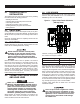
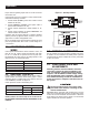


Table Of Contents

4
Proper conductor tightening torque values are on the decal inside
the enclosure door.
Connect power source load conductors to clearly marked transfer
mechanism terminal lugs as follows
1. Connect UTILITY (NORMAL) power source cables to switch
terminals N1, N2, (N3).
2. Connect EMERGENCY (STANDBY) source power cables to
transfer switch terminals E1, E2, (E3).
3. Connect customer LOAD leads to switch terminals T1, T2,
(T3).
4. Connect neutral conductors of UTILITY, EMERGENCY and
customer LOAD to the neutral block.
Conductors must be properly supported, of approved insulative
qualities, protected by approved conduit, and of the correct wire
gauge size in accordance with applicable codes.
Be sure to maintain proper electrical clearance between live metal
parts and grounded metal. Allow at least 1/2 inch through air or
1" over surface.
2.5 CONNECTING CONTROL
WIRES
Control system interconnections consist of UTILITY 1 and 2, and
leads 23 and 194. Control system interconnection leads must
be run in a conduit that is separate from the AC power lead.
Recommended wire gauge sizes for this wiring depends on the
length of the wire, as recommended below:
MAXIMUM WIRE LENGTH RECOMMENDED WIRE SIZE
1-115 ft (1-35m) No. 18 AWG.
116-185 ft (36-56m) No. 16 AWG.
186-295 ft (57-89m) No. 14 AWG.
296-460 ft (90-140m) No. 12 AWG.
2.6 AUXILIARY CONTACTS
If desired, there are Auxiliary Contacts on the transfer switch to
operate customer accessories, remote advisory lights, or remote
annunciator devices. A suitable power source must be connected
to the COMMON (C) terminal. See Figure 2.2.
Contact operation is shown in the following chart:
Switch Position
Utility Standby
Common to Normally Open Open Closed
Common to Normally Closed Closed Open
NOTE:
Auxiliary Contacts are rated 10 amps at 125 or 250 volts AC.
DO NOT EXCEED THE RATED VOLTAGE AND CURRENT OF THE
CONTACTS.
Figure 2.2 – Auxiliary Contacts
Side views shown in Utility position
2.7 OPTIONAL ACCESSORIES
Note any optional accessories that may be installed on the trans-
fer switch or are to be installed in the standby electric system in
conjunction with the switch. Complete the necessary connections
for these accessories.
3.1 FUNCTIONAL TESTS AND
ADJUSTMENTS
Following transfer switch installation and inter-
connection, inspect the entire installation care-
fully. A competent, qualified electrician should
inspect it. The installation should comply strictly
with all applicable codes, standards, and regula-
tions. When absolutely certain the installation is
proper and correct, complete a functional test of
the system.
Perform functional tests in the exact order
presented in this manual, or damage to the
switch could be done.
IMPORTANT: Before proceeding with functional tests, read and
make sure you understand all instructions and information in this
section. Also read the information and instructions of labels and
decals affixed to the switch. Note any options or accessories that
might be installed and review their operation.
Operation