
Product Manual
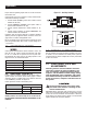


Table Of Contents

7
3. Three-phase only. Locate the 3 phase power monitor relay.
Verify the following:
LED Green and ON (For an explanation of all of the LED func-
tions, see the decal on the side of the power monitor.)
The factory setting is 80% of nominal voltage (208 Vac sys-
tems = 166 Vac dropout)
4. If the LED indicator is Red or not ON, then it will be necessary
to adjust the power monitor relay setting. Rotate the adjust-
ment potentiometer in a counter-clockwise direction until the
LED turns ON. At this point the 3 phase power monitor relay
is the most sensitive to irregular power line conditions.
NOTE:
If the power monitor does not operate properly, check that all
three voltages are present, and are of the correct voltage level
and phase rotation. To change phase rotation, turn off the utility
supply, interchange 2 of the utility power phases.
FAILURE TO TURN OFF THE UTILITY SUP-
PLY BEFORE WORKING ON THE UTILITY
CONNECTIONS OF THE ATS WILL RESULT
IN EXTREMELY DANGEROUS AND POSSIBLY
FATAL ELECTRICAL SHOCK.
5. When certain that UTILITY supply voltage is correct and
compatible with transfer switch ratings, turn OFF the UTILITY
supply to the transfer switch.
3.3.2 GENERATOR VOLTAGE CHECKS
1. On the generator panel, set the AUTO/OFF/MANUAL switch to
MANUAL position. The generator should crank and start.
2. Let the generator stabilize and warm up at no-load for at least
five minutes.
3. Set the generator's main circuit breaker (CB1) to its ON or
CLOSED position.
PROCEED WITH CAUTION. GENERATOR
OUTPUT VOLTAGE IS NOW BEING
DELIVERED TO TRANSFER SWITCH
TERMINALS. CONTACT WITH LIVE
TERMINALS RESULTS IN EXTREMELY
DANGEROUS AND POSSIBLY FATAL
ELECTRICAL SHOCK.
4. With an accurate AC voltmeter and frequency meter, check the
no-load, voltage and frequency.
Single-phase generator supply:
Measure across ATS terminal lugs E1 to E2; E1 to NEUTRAL
and E2 to NEUTRAL.
a. Frequency ....................................................60-62 Hz
b. Terminals E1 to E2 .......................................240-246 VAC
c. Terminals E1 to NEUTRAL ............................120-123 VAC
d. Terminals E2 to NEUTRAL ............................120-123 VAC
Three-phase generator supply:
Measure across ATS terminal lugs E1 to E2, E2 to E3 and E1
to E3.
Measure across ATS terminal lugs E1 to NEUTRAL, E2 to
NEUTRAL and E3 to NEUTRAL.
a. Frequency ....................................................60-62 Hz
b. Terminals E1-E2, E2-E3, E1-E3 .................... 208-212VAC, 235-
245VAC or 470-
485VAC
c. Terminals E1-N, E2-N, E3-N ......................... 120-122VAC, 136-
140VAC or 272-
282VAC
It will also be necessary to verify that the phase rotation of the util-
ity matches the phase rotation of the generator. This can be done
by using a phase rotation indicator.
Failure to do so may result in damage to cer-
tain rotary equipment.
5. When certain that UTILITY supply voltage is correct and
compatible with transfer switch ratings, turn OFF the UTILITY
supply to the transfer switch.
6. Set the generator’s main circuit breaker (CB1) to its OFF or
OPEN position.
7. Set the Auto/Off/Manual switch to the OFF position to shut
down the generator.
NOTE:
Do NOT proceed until generator AC output voltage and frequen-
cy are correct and within stated limits. If the no-load voltage is
correct but no-load frequency is incorrect, the engine governed
speed probably requires adjustment. If no-load frequency is
correct but voltage is not, the voltage regulator may require
adjustment.
Operation