Owner’s Manual Liquid-cooled, Prepackaged Standby Generators Models: 0043733, 0043734 & 0043735 (40 kW/Single-phase w/ 200 Amp Transfer Switch) 0046262, 0046263 & 0046264 ® POWER SYSTEMS, INC. ® (40 kW/Single-phase w/ 200 Amp Transfer Switch California Emissions) ! Not intended for use in critical life support applications. ! ONLY QUALIFIED ELECTRICIANS OR CONTRACTORS SHOULD ATTEMPT INSTALLATION!! DEADLY EXHAUST FUMES. OUTDOOR INSTALLATION ONLY! This manual should remain with the unit.
INTRODUCTION Thank you for purchasing the Guardian product line by Generac Power Systems. This model is a compact, high performance, liquid-cooled, engine-driven generator designed to automatically supply electrical power to operate critical loads during a utility power failure. This unit is factory installed in an all-weather, metal enclosure that is intended exclusively for outdoor installation.
Table of Contents Guardian Liquid-cooled 40 kW Generator Introduction ......................Inside Front Cover Read This Manual Thoroughly ......................IFC Contents ........................................................IFC Operation and Maintenance............................IFC How to Obtain Service ....................................IFC Authorized Dealer Locator Number ..................IFC Safety Rules ......................................................2 Section 1 – General Information..
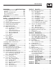
Important Safety Instructions Guardian Liquid-cooled 40 kW Generator ! SAVE THESE INSTRUCTIONS – The manufacturer suggests that these rules for safe operation be copied and posted in potential hazard areas. Safety should be stressed to all operators and potential operators of this equipment. ! ! SAVE THESE INSTRUCTIONS – This manual contains important instructions that should be followed during installation and maintenance of the generator and batteries.
Important Safety Instructions Guardian Liquid-cooled 40 kW Generator • Inspect the generator regularly, and promptly repair or replace all worn, damaged or defective parts using only factory-approved parts. • Before performing any maintenance on the generator, disconnect its battery cables to prevent accidental start-up. Disconnect the cable from the battery post indicated by a NEGATIVE, NEG or (–) first. Reconnect that cable last. • Never use the generator or any of its parts as a step.
Section 1 — General Information Guardian Liquid-cooled 40 kW Generator 1.1 UNPACKING/INSPECTION After unpacking, carefully inspect the contents for damage. • This standby generator set has been factory installed in an all-weather, metal enclosure that is intended exclusively for outdoor installation. If this generator is used to power electrical load circuits normally powered by a utility power source, code requires to install a transfer switch.
Section 1 — General Information Guardian Liquid-cooled 40 kW Generator 1.6 MAIN CIRCUIT BREAKER The generator’s main circuit breaker is included with the unit as shipped from the factory. The breaker for each unit is described as follows: Model Number Circuit Breaker Rating 0043733, 0043734, 0043735 0046262, 0046263, 0046264 200-amp breaker 200-amp breaker 1.
Section 1 — General Information Guardian Liquid-cooled 40 kW Generator 1.8.2 GENERATOR AND LOAD COMPATIBILITY The generator must be fully compatible with the rated voltage, number of phases and frequency of the connected electrical loads. The generator, connected electrical devices, or both, can be damaged if voltage, number of phases and frequency are not compatible.
Section 1 — General Information Guardian Liquid-cooled 40 kW Generator 1.10 ENGINE OIL RECOMMENDATIONS The unit has been filled with 15W-40 engine oil at the factory. Use a high-quality detergent oil classified “For Service CC, SD, SE or SF.” Detergent oils keep the engine cleaner and reduce carbon deposits.
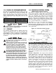
Section 2 — Installation Guardian Liquid-cooled 40 kW Generator STANDBY GENERATOR INSTALLATION DANGER Connecting this generator to an electrical system normally supplied by an electric utility shall be by means of a transfer switch (such as the Generac “GTS” type transfer switch), so as to isolate the electric system from the utility distribution system when the generator is operating.
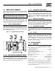
Section 2 — Installation Guardian Liquid-cooled 40 kW Generator Figure 2.1 – Basic Standby Electric System DANGER Do not connect the ground wire to any pipe that carries a flammable or explosive substance – FIRE or an EXPLOSION may result. Proper grounding helps protect personnel against electrical shock in the event of a ground fault condition in the generator or in connected electrical devices. In addition, grounding helps dissipate static electricity that often builds up in ungrounded devices.
Section 2 — Installation Guardian Liquid-cooled 40 kW Generator NOTE: When using a GTS switch, it is necessary to connect a 240V AC supply to N1 and N2 terminals of the generator to provide for battery charging. Wires T1, T2, 23 and 194 should not be connected. 2.7 BATTERY INSTALLATION DANGER ! Standby generators installed with automatic transfer switches will crank and start automatically when normal (utility) source voltage is removed or is below an acceptable preset level.
Section 2 — Installation Guardian Liquid-cooled 40 kW Generator 2.8.1 PRIOR TO INITIAL START-UP Prior to initially starting the generator, it must be properly prepared for use. Any attempt to crank or start the engine before it has been properly serviced with the recommended types and quantities of engine fluids (oil, coolant, fuel, etc.) may result in an engine failure. Before starting the generator for the first time, the installer must complete the following procedures.
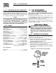
Section 3 — Operation Guardian Liquid-cooled 40 kW Generator 3.1 CONTROL CONSOLE COMPONENTS The components of a liquid-cooled generator control console (Figure 3.1) are as follows: Figure 3.1 – Control Console 3.1.6 AUTO/OFF/MANUAL SWITCH See Section 3.2. 3.1.7 FAULT INDICATOR LAMP This lamp goes ON when one or more of the following engine faults occurs and when engine shuts down. • Low oil pressure • Low coolant level • Overspeed 3.1.8 15 3.1.
Section 3 — Operation Guardian Liquid-cooled 40 kW Generator 3.2.2 “OFF” POSITION This switch position shuts down the engine. This position also prevents operation. 3.2.3 “MANUAL” POSITION Set the switch to Manual to crank and start the engine. Transfer to standby power will not automatically occur unless there is a utility failure. ! 3.3 With the switch set to AUTO, the engine may crank and start at any time without warning.
Section 4 — Maintenance Guardian Liquid-cooled 40 kW Generator Figure 3.2 – Engine Block Heater OUTLET • Place a sign on the generator’s control panel and on the transfer switch that indicates the day and time the generator will be exercising. NOTE: If the battery terminals are disconnected or the control panel fuse is removed, the exercise timer needs to be reset for automatic exercise operation. Figure 3.
Section 4 — Maintenance Guardian Liquid-cooled 40 kW Generator Figure 4.1 – Oil Dipstick and Fill Figure 4.2 – Oil Filter OIL DIPSTICK OIL FILL CAP OIL FILTER OIL DRAIN HOSE TO BASE 4.2 CHANGING THE ENGINE OIL AND FILTER 4.2.1 ENGINE OIL RECOMMENDATIONS Use oil of API Service Class SG, SH or SJ. The recommended oil grade for the engine is SAE 15W-40. 5. Apply a light coating of engine oil to the seal of new oil filter. Install the filter and tighten by hand only. DO NOT OVERTIGHTEN. 6.
Section 4 — Maintenance Guardian Liquid-cooled 40 kW Generator Figure 4.3 – Engine Air Cleaner DANGER Air Cleaner Standby generators installed with automatic transfer switches will crank and start automatically when normal (utility) source voltage is removed or is below an acceptable preset level.
Section 4 — Maintenance Guardian Liquid-cooled 40 kW Generator 4.6 COOLING SYSTEM 4.9 Air intake and outlet openings in the generator compartment must be open and unobstructed for continued proper operation. This includes such obstructions as high grass, weeds, brush, leaves and snow. Without sufficient cooling and ventilating air flow, the engine/generator quickly overheats, which causes it to shut down. The exhaust system of this product gets extremely hot and remains hot after shutdown.
Section 4 — Maintenance Guardian Liquid-cooled 40 kW Generator 2. Inside the generator set, the chance of rodent entry into the control panel is greatly reduced by the inclusion of adjustable wire connectors. Check that the wire connector screws are tight, thus closing off any gap between the access holes and the wires. 4.11 OUT OF SERVICE PROCEDURE 4.11.
Section 4 — Maintenance Guardian Liquid-cooled 40 kW Generator 4.12 SERVICE SCHEDULE ATTENTION: It is recommended that all service work be performed by your nearest Generac/Guardian Authorized Dealer. SYSTEM/COMPONENT X = Action R = Replace/Adjust as Needed * = Notify Dealer if Repair is Needed.
Section 5 — Troubleshooting Guardian Liquid-cooled 40 kW Generator 5.1 TROUBLESHOOTING GUIDE PROBLEM CAUSE CORRECTION The engine will not crank. 1. Fuse blown 2. Loose, corroded or defective battery cables 3. Defective starter contactor 4. Defective starter motor 5. Dead Battery 1. Replace fuse. 2. Tighten, clean or replace as necessary. 3. * 4. * 5. Charge or replace battery. The engine cranks but will not start. 1. Out of fuel 2. Defective fuel solenoid (FS) 3.
Section 6 — Electrical Data Guardian Liquid-cooled 40 kW Generator Mounting Dimensions - Drawing No. 0D5335 NOTE 7 220 [8.65"] STUB-UP AREA R677 [R26.66"] TYP STUB-UP AREA SEE NOTE 8 AND CHART ALT AIR 247 [9.73"] RECOMMENDED FUEL/ELECTRICAL STUB-UPS (SEE TOP VIEW) DESCRIPTION AC LOAD LEAD CONDUIT INSIDE STUB-UP FOR FUEL CONNECTIONS 204 [8.03"] (LEFT) INSIDE BASE A1 C NOTE: 839 [33.01 TYP 794 [31.28"] STUB-UP AREA A1 FUEL SYSTEM SET UP WITH OUTSIDE STUB UPS (SEE LEFT SIDE VIEW).
Section 6 — Electrical Data 219 150 86 85 69 68 56 229 4 15 15 15 14 14 13 79 0 0 0 (Model No. 0043733, 0043734 & 0043735) Guardian Liquid-cooled 40 kW Generator Electrical Schematic (Stepper Motor) – Drawing No. 0A5858 TS1 GCB BLACK RED P/N 98647 S16 BLUE HZ BLUE LEGEND GCB - GOVERNOR CONTROL BOARD HZ - FREQUENCY METER TB1 - TERMINAL BLOCKS 22 Generac® Power Systems, Inc.
12 EH 13 A LEGEND 14 14 13 10 14 85 85 0 56 85 85 GCU 0 56 AM - METER, AC OUTPUT CURRENT AVR - AUTOMATIC VOLTAGE REGULATOR BVM - METER, BATTERY VOLTAGE CAP - CAPACITOR CB1 - CIRCUIT BREAKER- EXCITATION CP - CONNECTION, LOWER PANEL D1 - DIODE- 600V, 12A EH - ENGINE HARNESS CONNECTION F1 - FUSE 15A F2 - FUSE 7.
TO ENGINE (CONNECTOR EH) TO LOWER PANEL (CONNECTOR CP) 29 1 4 13 14 14 0 4 162 1 0 85 56 14 S15 A T1 17 S15 T2 16 RED BLACK GCU BLUE BLUE 225A 176 RED N2 23 194 183 178 N2 23 194 183 178 W X B J BLACK T1 T2 BLUE T1 225A T TO GOVERNOR ACTUATOR CONTROLLER CONNECTOR BLUE BLUE 23 176 15A 15C 15A N1 O O O O O 0 194 15C 15A F2 SW2 N1 0 X 19 - 14 O O X O O X X 1 2 3 OFF F X X 3 15 E 4 12 POSITION HZ RED 14 9 15 - 14 15 - 18 12 - 3 12 -
6 NB 57 SCHEMATIC 120/240-V.
14 160 13 14 14 14 13 14 161 7 ACT- 161 BAT- 0 EH 6 5 4 85 85 0 56 MPU+ 85 79 85 MPU- 0 0 BAT+ 14 56 MPU SHIELD 0 N1 56 0 14 N2 AVR N1 N2 BLACK RED 13 85 N2 14 85 85 14 3 5 6 2 1 4 6 1 0 TS2 56 S16 S15 4 162 13 BLACK 4 162 TR1 GRD RED D1 BLACK 29 2 S16 13 0 162 13 4 15 17 16 T2 T1 T2 14 0 0 S15 0 0 0 1 14 14 4 14 0 0 13 4 14 4 56 56 56 4 4 85 85 BLUE 12 11 10 9 PCB T1 0 14 14 14 14 14 4 13 USE BLUE WIRE
TO ENGINE (CONNECTOR EH) TO LOWER PANEL (CONNECTOR CP) 4 0 4 S3 57 M N 162 0 S15 A T1 17 7 S15 T2 16 PCB 5 56 3 15 E 4 10 12 1 2 3 OFF F POSITION HZ RED 14 9 178 23 176 PFC 225A 15C BAT- BAT+ 176 0 14 T1 N1 N2 23 194 183 178 N1 N2 23 194 183 178 S T W X B J T1 T2 BLUE SW2 225A 15C T1 0 194 15C 15E 15A T2 0 15 - 18 19 - 16 19 - 14 X INDICATES CLOSED 12 - 7 12 - 11 2-3 2-7 2 - 11 CONTACTS VM 11 178 T2 67 AM + 0 64 65 D 229 239
Section 6 — Electrical Data Guardian Liquid-cooled 40 kW Generators Wiring Diagram - Drawing No.
Section 6 — Electrical Data Guardian Liquid-cooled 40 kW Generators Wiring Diagram - Drawing No.
Section 7 — Exploded Views and Parts Lists 33 23 25 3 BLACK 25 25 25 24 1 25 35 37 36 26 30 Generac® Power Systems, Inc. 30 31 12 5 34 16 17 2 38 13 17 16 11 10 9 12 29 RED 7 9 2 TO STARTER SOLENOID 39 21 4 32 6 5 18 22 25 20 15 To Oil Drain On Oil Pan. 14 15 7 8 12 19 11 10 18 Guardian Liquid-cooled 40 kW Generators Mounting Base - Drawing No.
Section 7 — Exploded Views and Parts Lists Guardian Liquid-cooled 40 kW Generators Mounting Base - Drawing No. 0E2384-A ITEM 1 2 3 4 5 6 7 8 9 10 11 12 13 14 15 16 17 18 19 20 21 22 23 24 25 26 27 28 29 30 31 32 33 34 35 36 37 38 39 PART NO.
Section 7 — Exploded Views and Parts Lists Guardian Liquid-cooled 40 kW Generators Compartment - Drawing No. 0D8992 28 26 13 29 23 32 33 34 25 31 30 15 39 22 11 9 29 12 24 8 36 11 11 4 7 1 42 10 3 12 16 5 1 5 19 3 18 6 17 11 5 10 BASE FRAME 29 32 Generac® Power Systems, Inc.
Section 7 — Exploded Views and Parts Lists Guardian Liquid-cooled 40 kW Generators Compartment - Drawing No. 0D8992 ITEM 1 3 4 5 6 7 8 9 10 11 12 13 15 16 17 18 19 20 21 22 23 24 25 26 28 29 30 31 32 33 34 35 36 39 42 43 44 PART NO. QTY.
34 Generac® Power Systems, Inc. 12 VIEW A-A 13 59 18 17 16 35 5 6 20 19 18 49 50 21 64 36 42 60 A A 9 37 60 61 61 41 51 52 53 58 39 3 51 52 53 58 43 23 29 26 28 24 25 27 45 46 47 48 18 49 50 62 63 - 15 52 53 1 + 14 54 55 56 57 4 18 49 50 3 22 30 31 32 2 EVERY 7 DAYS, AT TIME SET. SET 81988 IM E 33 V PANEL FACE A 3 0 Hz 1 INSIDE. 34 Section 7 — Exploded Views and Parts Lists (Model No.
Section 7 — Exploded Views and Parts Lists (Model No. 0043733, 0043734 & 0043735) Guardian Liquid-cooled 40 kW Generator Control Panel 4.3L – Drawing No. 0D4995-F ITEM PART NO. QTY.
Section 7 — Exploded Views and Parts Lists (Model No. 0046262, 0046263 & 0046264) Guardian Liquid-cooled 40 kW Generator Control Panel – Drawing No. 0D6978-C 36 Generac® Power Systems, Inc.
Section 7 — Exploded Views and Parts Lists (Model No. 0046262, 0046263 & 0046264) Guardian Liquid-cooled 40 kW Generator Control Panel – Drawing No. 0D6978-C ITEM PART NO. QTY.
Section 7 — Exploded Views and Parts Lists Guardian Liquid-cooled 40 kW Generators Connection Box – Drawing No. 0D8848-B BOTTOM OF CONTROL PANEL REF. 35 37 36 2 1 18 4 37 3 35 11 4 34 33 36 12 37 38 ALT. LEADS & SENSING WIRE 60 0 59 58 13 ALT.
Section 7 — Exploded Views and Parts Lists Guardian Liquid-cooled 40 kW Generators Connection Box – Drawing No. 0D8848-B ITEM 1 2 4 6 9 10 11 12 13 18 29 30 31 32 33 34 35 36 37 38 40 42 43 44 45 46 47 48 49 50 52 53 54 55 56 57 58 59 60 PART NO.
40 Generac® Power Systems, Inc. 6 9 18 35 4 2 19 5 20 32 17 16 7 DO NOT ROTATE ENGINE DURING THIS ADJUSTMENT. CAUTION: 15 19 30 18 31 3 TO ENGINE FLYWHEEL 35 THREAD IN SENSOR (6) UNTIL CONTACT IS MADE WITH RING GEAR, THEN BACK OFF 1/2 TO 3/4 TURN AND TIGHTEN NUT.
Section 7 — Exploded Views and Parts Lists Guardian Liquid-cooled 40 kW Generators Generator – Drawing No. 0D9490 ITEM PART NO. QTY.
Section 7 — Exploded Views and Parts Lists Guardian Liquid-cooled 40 kW Generators Engine – Drawing No. 0D6980-B 42 Generac® Power Systems, Inc.
Section 7 — Exploded Views and Parts Lists Guardian Liquid-cooled 40 kW Generators Engine – Drawing No. 0D6980-B ITEM 1 2 3 4 6 8 9 10 11 12 13 14 15 16 17 18 19 20 21 22 23 24 25 26 27 28 29 30 31 32 33 34 35 36 37 38 39 40 41 42 43 * * PART NO.
Section 7 — Exploded Views and Parts Lists 11 36 13 24 23 45 10 32 31 6 5 19 33 31 4 35 21 46 40 37 34 20 43 4 22 40 43 25 40 41 34 3 14 8 7 44 2 27 28 30 47 9 1 12 16 26 17 38 15 Guardian Liquid-cooled 40 kW Generators Engine – Drawing No. 0A4304-L 44 Generac® Power Systems, Inc.
Section 7 — Exploded Views and Parts Lists Guardian Liquid-cooled 40 kW Generators Engine – Drawing No. 0A4304-L ITEM PART NO. QTY.
Section 7 — Exploded Views and Parts Lists 11 19 18 33 34 35 31 30 KIT PART NO. 0D7948 20 32 KIT PART NO. 0D7947 37 38 39 16 36 14 27 40 29 1 16 46 Generac® Power Systems, Inc. KIT PART NO. 0D8121 9 10 "A" 10 15 27 22 7 22 3 24 23 17 17 TO "A" 10 21 Guardian Liquid-cooled 40 kW Generators 4.3L Radiator – Drawing No.
Section 7 — Exploded Views and Parts Lists Guardian Liquid-cooled 40 kW Generators 4.3L Radiator – Drawing No. 0D7992-D ITEM 1 2 3 4 5 6 7 9 10 11 12 14 15 16 17 18 19 20 21 22 23 24 27 29 30 * 31 * 32 * 33 * 34 * 35 * 36 ** 37 ** 38 ** 39 ** 40 PART NO.
Section 7 — Exploded Views and Parts Lists (Model No. 0043733, 0043734 & 0043735) Guardian Liquid-cooled 40 kW Generators 4.3L Exhaust – Drawing No. 0E0704-A 20 19 1 21 21 20 2.5" DIA. CLAMP ASSEMBLY 2 24 21 20 24 19 23 19 6 19 22 19 9 19 19 3 13 19 19 18 8 14 7 16 18 15 13 5 13 14 4 15 10 TO COMPARTMENT FRONT TO ENGINE 11 15 TO ENGINE 18 14 5 4 12 10 ITEM 1 2 3 4 5 6 7 8 9 10 11 12 PART NO.
Section 7 — Exploded Views and Parts Lists Guardian Liquid-cooled 40 kW Generators 4.3L Air Cleaner – Drawing No. 0E0712 1 2 3 4 5 6 ITEM 1 2 3 4 5 6 7 8 PART NO. 037561 0A4632A 0A4637 0A4632B 062522 022127 057796 057795 QTY. 1 1 1 1 1 1 1 1 7 8 DESCRIPTION NUT WING 1/4-20 NYLK PLATE AIR CLEANER TOP FILTER AIR 11.5" CA326 PLATE,AIR CLEANR BOT STUD TH 1/4-20 X 3 G2 ZNC FULL NUT HEX 1/4-20 STEEL GROMMET CONNECTOR C/C VENT Generac® Power Systems, Inc.
Section 7 — Exploded Views and Parts Lists 15 2 10 8 9 24 5 24 6 7 6 19 42 TO VALVE COVER 37 38 36 3 3 1 3 34 35 TO INTAKE MANIFOLD 39 40 2 24 30 29 20 21 3 2 TO STEPPER MOTOR 17 25 2 24 4 1 18 28 14 16 11 17 18 12 27 23 13 11 12 13 11 12 13 (Model No. 0043733, 0043734 & 0043735) Guardian Liquid-cooled 40 kW Generators 4.3L Nat. Gas Fuel System – Drawing No. 0E0714 50 Generac® Power Systems, Inc.
Section 7 — Exploded Views and Parts Lists (Model No. 0043733, 0043734 & 0043735) Guardian Liquid-cooled 40 kW Generators 4.3L Nat. Gas Fuel System – Drawing No. 0E0714 ITEM 1 2 3 4 5 6 7 8 9 10 11 12 13 14 15 16 17 18 19 20 21 23 24 25 26 27 28 29 30 31 32 33 34 35 36 37 38 39 40 41 42 PART NO.
Section 7 — Exploded Views and Parts Lists (Model No. 0046262, 0046263 & 0046264) Guardian Liquid-cooled 40 kW Generators 4.3L Nat. Gas Fuel System – Drawing No. 0E1338 ATTACH TO FAN SCROLL 28 19 29 24 43 18 2 25 22 ASSEMBLY P/N 0D3509 40 7 6 5 24 2 4 4 33 30 24 8 2 12 31 46 9 11 32 3 12 1 12 45 34 35 2 36 17 10 44 39 41 18 17 13 24 37 TO INTAKE MANIFOLD TO VALVE COVER 21 20 11 1 12 38 27 13 23 15 16 52 Generac® Power Systems, Inc.
Section 7 — Exploded Views and Parts Lists (Model No. 0046262, 0046263 & 0046264) Guardian Liquid-cooled 40 kW Generators 4.3L Nat. Gas Fuel System – Drawing No. 0E1338 ITEM PART NO.
Section 7 — Exploded Views and Parts Lists (Model No. 0046262, 0046263 & 0046264) Guardian Liquid-cooled 40 kW Generators Exhaust – Drawing No. 0E1347-A 54 Generac® Power Systems, Inc.
Section 7 — Exploded Views and Parts Lists (Model No. 0046262, 0046263 & 0046264) Guardian Liquid-cooled 40 kW Generators Exhaust – Drawing No. 0E1347-A ITEM 1 2 3 4 5 6 7 8 9 10 11 12 13 14 15 16 18 19 20 21 22 23 24 25 26 27 28 29 30 31 32 33 34 35 36 PART NO.
Section 7 — Exploded Views and Parts Lists (Model No. 0043733, 0043734 & 0043735) Guardian Liquid-cooled 40 kW Generators Electronic Governor – Drawing No. 0A2615-F ITEM 1 2 3 4 5 9 11 12 13 14 15 16 17 18 19 20 21 22 23 24 PART NO. 098290 0A3439 098958A 021888 082508 036409 043146 098941A 098942A 098225 022097 064526 029333A 074031 051716 049226 076040 098647 036409 0C2184 QTY.
Section 7 — Exploded Views and Parts Lists Guardian Liquid-cooled 40 kW Generators Engine Coolant Heater – Drawing No. 0E2352 TO THERMOSTAT HOUSING 1 7 2 6 TO ENGINE BLOCK 3 4 4 5 8 6 9 2 10 9 11 12 8 12 13 ITEM 1 2 3 4 5 6 7 8 9 10 11 12 13 14 15 PART NO. **0C4905 **057822 **077043E **050967 0A6283 057822 053660 042568 022473 084918A *084918B 084427 022097 049813 055934D 077043A QTY. 1 2 1 1 1 2 1 4 4 1 1 1 4 2 1 1 DESCRIPTION BARBED EL 45 FITTING CLAMP HOSE #8 .53-1.
Section 8 – Notes Guardian Liquid-cooled 40 kW Generators 58 Generac® Power Systems, Inc.
Section 8 – Notes Guardian Liquid-cooled 40 kW Generators Generac® Power Systems, Inc.
Section 9 – Warranty Guardian Liquid-cooled 40 kW Generators CALIFORNIA EMISSION CONTROL WARRANTY STATEMENT YOUR WARRANTY RIGHTS AND OBLIGATIONS The California Air Resources Board (CARB) and Generac Power Systems, Inc. (Generac) are pleased to explain the Emission Control System Warranty on your new engine.* In California, new utility, and lawn and garden equipment engines must be designed, built and equipped to meet the state’s stringent anti-smog standards.
Section 9 – Warranty Guardian Liquid-cooled 40 kW Generators EMISSION CONTROL SYSTEM WARRANTY Emission Control System Warranty (ECS Warranty) for 1995 and later model year engines: (a) Applicability: This warranty shall apply to 1995 and later model year engines. The ECS Warranty Period shall begin on the date the new engine or equipment is purchased by/delivered to its original, end-use purchaser/owner and shall continue for 24 consecutive months thereafter.
Section 9 – Warranty Guardian Liquid-cooled 40 kW Generators GENERAC POWER SYSTEMS STANDARD "TWO YEAR" LIMITED WARRANTY FOR GUARDIAN “EMERGENCY AUTOMATIC STANDBY GENERATORS” For a period of two years from the date of original sale, Generac Power Systems, Inc.