Owner’s Manual and Installation Instructions Air-cooled Recreational Vehicle Generators Model: 004709-0 QUIETPACT 40G This manual should remain with the unit.
INTRODUCTION Thank you for purchasing this model by Generac Power Systems Inc. This model is designed and manufactured to supply electrical power for recreational vehicles. READ THIS MANUAL THOROUGHLY If any portion of this manual is not understood, contact the nearest Authorized Service Dealer for starting, operating and servicing procedures.
Table of Contents Recreational Vehicle Generator Part – Owner’s Manual Part II – Installation Instructions Introduction ........................................Inside Front Cover Safety Rules ..................................................................... 18 Read This Manual Thoroughly ................................. IFC Section 1 – General Information ................................ 20 Contents .................................................................. IFC 1.
Safety Rules Recreational Vehicle Generator SAVE THESE INSTRUCTIONS – The manufacturer suggests that these rules for safe operation be copied and posted in potential hazard areas of the recreational vehicle. Safety should be stressed to all operators and potential operators of this equipment. • WARNING: The engine exhaust from this product contains chemicals known to the state of California to cause cancer, birth defects or other reproductive harm.
Safety Rules Recreational Vehicle Generator • When working on this equipment, remain alert at all times. Never work on the equipment when physically or mentally fatigued. • Inspect the generator regularly, and contact the nearest Authorized Service Dealer immediately for parts needing repair or replacement. • Before performing any maintenance on the generator, disconnect its battery cables to prevent accidental start up. Disconnect the cable from the battery post indicated by a NEGATIVE, NEG or (–) first.
Section 1 – General Information Recreational Vehicle Generator 1.1 GENERATOR IDENTIFICATION Please record the following information from the generator DATA DECAL or information decal. 1. 2. 3. 4. 5. 6. 7. 8. 9. 10. 1. Model Number _____________________ 2. Serial Number __________________ 3. kW Rating _________________________ 4.
Section 1 – General Information Recreational Vehicle Generator 1.2 GENERATOR APPLICABILITY These generators have been designed and manufactured for supplying electrical power for recreational vehicles. Do not modify the generator or use it for any application other than for what it was designed. If there are any questions pertaining to its application, contact an Authorized Service Dealer. Do not use the unit until advised by a competent authority.
Section 1 – General Information Recreational Vehicle Generator 1.5.5 GENERATOR The manufacturer does not recommend using any gasoline containing alcohol (such as “gasohol”). If using any gasoline containing alcohol, it must not contain more than 10 percent ethanol, and it must be removed from the generator during storage. Do NOT use any gasoline containing methanol. If using gasoline with alcohol, inspect more frequently for fuel leaks and other abnormalities. 1.5.
Section 2 – Operation Recreational Vehicle Generator 2.1 GENERATOR CONTROL PANEL The following features are mounted on the generator control panel (Figure 2.1): Figure 2.1 – Generator Control Panel CONTROL CENTER S T A R T F U E L S T O P P R IM E C .B . 3 0 A FUS E 7. 5 A 2.2 OPTIONAL REMOTE START/STOP PANEL A remote mounted Start/Stop Panel is available that allows starting and stopping the generator engine conveniently from inside the vehicle.
Section 2 – Operation Recreational Vehicle Generator 2.4.2 ENGINE LUBRICATION Have the engine crankcase properly serviced with the recommended oil before starting. Refer to sections "Engine Oil Requiremtents", "Checking the Engine Oil Level" and "Changing the Engine Oil and/or Oil Filter" for oil servicing procedures and recommendations. attempt to crank or start the engine before Any it has been properly serviced with the recommended oil may result in an engine failure. 2.4.
Section 2 – Operation Recreational Vehicle Generator 2.6 STOPPING THE GENERATOR 1. Turn OFF all electrical loads using the means provided (such as a main circuit breaker or transfer switch). 2. Let generator run at no-load for a few minutes, to stabilize internal engine generator temperatures. 3. Place the Start/Stop switch in its STOP position. 2.
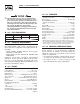
Section 2 – Operation Recreational Vehicle Generator 2.9.3 FIELD BOOST The Controller Circuit Board houses a field boost diode and resistor that are not part of the automatic choke circuit. These two components are part of a “field boost” circuit (Figure 2.3). During engine cranking only, a positive DC (battery) voltage is delivered through the diode, resistor, brushes and slip rings, to the generator rotor. Application of this voltage to the rotor “flashes the field” whenever it is started.
Section 3 – Maintenance Recreational Vehicle Generator 3.1 CHECKING THE ENGINE OIL LEVEL For oil capacities and requirements, see “Engine Oil Requirements”. Check the engine crankcase oil level at least every eight hours of operation, or before each use. To check the engine oil level, proceed as follows (see Figure 3.1): 1. Be sure the generator is as level as possible. 2. Remove the dipstick and wipe it dry with a clean, lint-free cloth. 3. Install and tighten the dipstick cap; then, remove it again.
Section 3 – Maintenance Recreational Vehicle Generator NOTE: Check the oil level and fill to the “FULL” mark after checking for leaks. The filter will retain some oil. 3.3 MAINTAINING THE ENGINE AIR CLEANER 3.3.1 CLEANING THE FOAM PRECLEANER Clean and re-oil the foam precleaner every three months or every 25 hours of operation, whichever occurs first. Service the foam precleaner more frequently if operating the generator in extremely dusty or dirty conditions. Use the following procedure (Figure 3.
Section 3 – Maintenance Recreational Vehicle Generator Figure 3.4 – Setting the Spark Plug Gap Clean and inspect the spark arrestor as follows: • Remove the screen retaining bracket by removing the screw. • Slide the spark arrestor screen out from the tail pipe. • Inspect screen and replace if torn, perforated or otherwise damaged. DO NOT USE a defective screen. If screen is not damaged, clean it with commercial solvent. • Replace the screen and the retaining bracket. Figure 3.
Section 3 – Maintenance Recreational Vehicle Generator 3.9 BATTERY MAINTENANCE All lead-acid batteries will discharge when not in use. The generator battery should be inspected as follows: not open or mutilate the battery. Released Do electrolyte has been known to be harmful to the skin and eyes, and to be toxic. 3.9.1 WEEKLY • Inspect the battery posts and cables for tightness and corrosion. Tighten and clean as necessary.
Section 3 – Maintenance Recreational Vehicle Generator 4. Attach a tag to the engine indicating the viscosity and classification of the oil in the crankcase. 5. Remove the spark plug and pour two or three tablespoons of clean, fresh engine oil into the spark plug threaded openings. Reinstall and tighten the spark plug. 6. Remove the battery and store it in a cool, dry room on a wooden board. Never store the battery on any concrete or earthen floor. 7. Clean and wipe the entire generator. Figure 3.
Section 4 – Notes Recreational Vehicle Generator 16
PART II – INSTALLATION INSTRUCTIONS DANGER ONLY QUALIFIED ELECTRICIANS OR CONTRACTORS SHOULD ATTEMPT INSTALLATION!
Safety Rules Recreational Vehicle Generator DANGER: For fire safety, installation of a generator into a recreational vehicle must comply strictly with article 551, NFPA 70; ANSI C1-1975; AND, ANSI A119.2-1975/NFPA 501C “Standard for Recreational Vehicles” (Part 3, “Installation of Electrical Systems”). In addition, installation must comply with the manufacturer’s instructions and recommendations.
Safety Rules Recreational Vehicle Generator ELECTRICAL HAZARDS FIRE HAZARDS • The generator covered by this manual produces dangerous electrical voltages and can cause fatal electrical shock. Avoid contact with bare wires, terminals, connections, etc., while the unit is running. Ensure all appropriate covers, guards and barriers are in place before operating the generator. If work must be done around an operating unit, stand on an insulated, dry surface to reduce shock hazard.
Section 1 – General Information Recreational Vehicle Generator 1.1 PURPOSE AND SCOPE OF THE MANUAL These Installation Instructions have been prepared especially for the purpose of familiarizing installers and owners of the applicable equipment with the product's installation requirements. Give serious consideration to all information and instructions in the manual, both for safety and for continued reliable operation of the equipment.
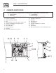
Section 1 – General Information Recreational Vehicle Generator Figure 1.2 – Major Features and Dimensions (Drawing No.
Section 2 – Installation Recreational Vehicle Generator 2.1 LOCATION AND SUPPORT 2.1.1 GENERATOR LOCATION The most desirable location for the generator set is between the vehicle's main frame members. However, this is seldom possible. Most units must be installed on the side of the vehicle and are difficult to reinforce. Many recreational vehicles have been factory equipped with an area for the generator set. Some vehicles may even have a generator compartment provided by the vehicle manufacturer.
Section 2 – Installation Recreational Vehicle Generator Figure 2.2 – Typical Suspended Mounting System Figure 2.4 – Clearances Plywood Compartment 1/2" Clearance on Top 1" Clearance in Back GENERATOR SUPPORT FRAME (MODEL 004718-0) 1" Each Side Insulation 1/2" in Front GENERATOR MOUNTING HOLES FOR 5/16" - 18 BOLTS (6 PLACES) 2.1.4 GENERATOR RESTRAINT Use four 5/16"-18 hardened steel bolts (Grade 5) to fasten the generator to the supporting frame or the support tubing.
Section 2 – Installation Recreational Vehicle Generator • If constructing a compartment, line the exterior (underside) of the compartment floor with 26gauge galvanized steel. • All seams, splices and joints of the compartment walls (unless vapor tight by design) should be caulked to prevent poisonous, flammable or explosive vapors from entering the vehicle interior. NOTE: Caulking must be done so that the caulking material will stay in place permanently.
Section 2 – Installation Recreational Vehicle Generator Figure 2.7 – Typical Noise Abatement 2.3 COOLING AND VENTILATING AIR It is absolutely essential that an adequate flow of air for cooling, ventilating and engine combustion be supplied to the generator set. Without sufficient airflow, the engine/generator quickly overheats. Such overheating can cause serious operating difficulties and also may cause fire and personal injury.
Section 2 – Installation Recreational Vehicle Generator Figure 2.
Section 2 – Installation Recreational Vehicle Generator 2.3.2 TESTING THE INSTALLATION 2.4.1 FUEL TANK The manufacturer recommends testing the installation to be sure adequate cooling airflow is available to the unit before placing the unit into service. If the unit shows signs of overheating, enlarge the air openings. Never place a unit into service until absolutely certain that cooling and ventilation is adequate.
Section 2 – Installation Recreational Vehicle Generator 2.4.2.2 Flexible Fuel Line 2.5.1 SPARK ARRESTOR Use an approved flexible length of fuel hose between the generator fuel inlet connection and rigid fuel lines. This prevents breaking of the line caused by vibration, shifting, settling or movement. The following rules apply: This spark arrestor assembly meets code and standard requirements of the U.S. Forest Service. Use only mufflers and parts approved by the manufacturer.
Section 2 – Installation Recreational Vehicle Generator 2.5.2 EXHAUST SYSTEM SAFETY • Maintain a clearance of at least 3 inches (76 mm) between exhaust system parts and any combustible material (such as wood, felt, cotton, organic fibers or other like material). If the 3-inch (76 mm) clearance cannont be maintained, locate, insulate or shield the exhaust part(s) so that the temperature of any combustible material is not raised more than 117° F (65° C) above the ambient air temperature.
Section 2 – Installation Recreational Vehicle Generator Figure 2.13 – Generator AC Output Leads 2.6.4 CONDUIT Route the connections between the generator and the junction box through approved, flexible conduit. The following general rules apply: 483.1 REMOTE PANEL CONNECTOR AC OUTPUT HARNESS FUEL FILTER • Cut wiring to the required length and allow extra wire for junction box connections. • Carefully prepare conduit ends to prevent sharp edges from cutting through wiring insulation.
Section 2 – Installation Recreational Vehicle Generator Figure 2.15 – Installation With Isolation Receptacle 2.6.7 GROUND FAULT CIRCUIT INTERRUPTERS The National Electrical Code (NFPA 70, 551-7) requires that ground fault circuit interrupters (GFCIs) be installed on all external and some internal electrical receptacles. Contact the dealer for recommendations. 2.7 BATTERY INSTALLATION 2.7.
Section 2 – Installation Recreational Vehicle Generator 2.7.3 BATTERY CABLE CONNECTIONS Figure 2.17 – Remote Panel Plug-in Receptacle 1. Connect the battery cable from the battery post or terminal indicated by a POSITIVE, POS or (+) to the lug on the starter contactor (Figure 2.16). NOTE: Check to be sure the battery cable boot for the starter cable has been installed. 2. Connect the battery cable from the battery post indicated by a NEGATIVE, NEG or (-) to the frame ground connection (Figure 2.16). 3.
Section 3 – Post-Installation Start-up Adjustments Recreational Vehicle Generator 3.1 POST INSTALLATION TESTS The air-cooled generator set was factory tested and adjusted. It should not be required to adjust the unit any further except under special circumstances. not make any unnecessary adjustments. Do Factory settings are correct for most applications. When making adjustments, however, be careful to avoid overspeeding the engine. 3.
Section 3 – Post-Installation Start-up Adjustments Recreational Vehicle Generator 3.5 INSTALLATION CHECKLIST EXHAUST SYSTEM LOCATION AND SUPPORT ❑ Exhaust system complies with all applicable codes. ❑ Generator is properly located. ❑ Exhaust system is properly and safely installed. ❑ Generator is properly supported. ❑ Generator is properly restrained. ELECTRICAL CONNECTIONS GENERATOR COMPARTMENT ❑ Connections comply with local code requirements and all National Electrical Codes.
Section 4 – Troubleshooting Recreational Vehicle Generator TROUBLESHOOTING GUIDE Problem Cause Correction The engine will not crank. 1. Fuse blown 2. Loose, corroded or defective battery cables 3. Defective engine Start/Stop switch 4. Defective starter contactor 5. Defective starter motor 6. Low or defective battery 1. Replace fuse. 2. Tighten, clean or replace as necessary. 3. Replace Start/Stop switch. The engine cranks but will not start. 1. Out of fuel 2. Defective fuel pump 3.
Section 5 — Electrical Data Recreational Vehicle Generator Electrical Schematic and Wiring Diagram – Drawing No.
Section 5 — Electrical Data Recreational Vehicle Generator Electrical Schematic and Wiring Diagram – Drawing No.
Section 6 — Exploded Views and Parts Lists Recreational Vehicle Generator Enclosure – Drawing No.
Section 6 — Exploded Views and Parts Lists Recreational Vehicle Generator Enclosure – Drawing No. 0D8352-K ITEM PART NO. QTY.
Section 6 — Exploded Views and Parts Lists Recreational Vehicle Generator Generator – Drawing No.
Section 6 — Exploded Views and Parts Lists Recreational Vehicle Generator Generator – Drawing No. 0D8353-L ITEM 1 2 3 4 5 6 7 8 9 10 11 12 13 14 15 16 17 18 19 20 21 22 23 24 25 26 27 28 29 30 31 32 33 34 35 36 37 38 39 41 42 PART NO.
Section 6 — Exploded Views and Parts Lists Recreational Vehicle Generator Control Panel – Drawing No.
Section 6 — Exploded Views and Parts Lists Recreational Vehicle Generator Control Panel – Drawing No. 0D8354-H ITEM 1 2 3 4 5 6 7 8 9 10 11 12 13 14 15 16 17 18 19 20 21 22 23 24 25 26 27 28 29 30 31 32 33 34 35 36 37 38 39 PART NO.
Section 6 — Exploded Views and Parts Lists Recreational Vehicle Generator GN-220 H/SH Engine – Drawing No.
Section 6 — Exploded Views and Parts Lists Recreational Vehicle Generator GN-220 H/SH Engine – Drawing No. 0D8355-AA Part 1 ITEM PART NO. QTY. DESCRIPTION 0D8433 0C1069 0C1069 090965F 0G6468 1 10 11 1 1 4 5 6 081810 083312 0D8400 1 1 1 7 8 9 10 11 12 13 14 15 16 17 0C8917A 0C8798A 045756 082774 022129 081990 0D9004A 0E7585 1 1 9 1 2 2 1 1 GUARD, FAN SCREW, HHTT M6-1.0 X 8mm (04709 ONLY) BLOWER HOUSING BLOWER HOUSING 220RV (04709 ONLY) NUT, HEX M16-1.
Section 6 — Exploded Views and Parts Lists Recreational Vehicle Generator GN-220 H/SH Engine – Drawing No.
Section 6 — Exploded Views and Parts Lists Recreational Vehicle Generator GN-220 H/SH Engine – Drawing No. 0D8355-AA Part 2 ITEM PART NO.
Section 7 – Warranty Recreational Vehicle Generator CALIFORNIA AND FEDERAL EMISSION CONTROL WARRANTY STATEMENT YOUR WARRANTY RIGHTS AND OBLIGATIONS The California Air Resources Board (CARB) and the United States Environmental Protection Agency (EPA), together with Generac Power Systems, Inc. (Generac), are pleased to explain the Emission Control System Warranty on your new engine.
Section 7 – Warranty Recreational Vehicle Generator EMISSION CONTROL SYSTEM WARRANTY Emission Control System Warranty (ECS Warranty) for 1997 and later model year engines: (a) Applicability: This warranty shall apply to 1997 and later model year engines. The ECS Warranty Period shall begin on the date the new engine or equipment is purchased by/delivered to its original, end-use purchaser/owner and shall continue for 24 consecutive months thereafter.
Section 7 – Warranty Recreational Vehicle Generator GENERAC POWER SYSTEMS’ THREE-YEAR LIMITED WARRANTY FOR GUARDIAN RECREATIONAL VEHICLE GENERATORS NOTE: ALL UNITS MUST BE INSTALLED BY GENERAC POWER SYSTEMS AUTHORIZED SERVICE FACILITIES. For a period of 3 (three) years of operation from the date of original sale, Generac Power Systems, Inc.