Automatic Transfer Switch Owner’s Manual ATS Service Entrance HS Type Transfer Switch Models: 005036-0, 100 Amp, 250 Volts and 004945-1, 200 Amp, 250 Volts This manual should remain with the unit.
IMPORTANT SAFETY INSTRUCTIONS followed during installation and maintenance of the generator and batteries. SAVE THESE INSTRUCTIONS - This manual contains important instructions that should be operate or service this equipment. Also read the instructions and information on tags, install, decals, and labels that may be affixed to the transfer switch. Replace any decal or label that SAVE THESE INSTRUCTIONS! Read the following information carefully before attempting to is no longer legible.
Table of Contents • Competent, qualified personnel should install, operate and service this equipment. Adhere strictly to local, state and national electrical and building codes. When using this equipment, comply with regulations the National Electrical Code (NEC), CSA Standard; C22.1 Canadian Electric Code and Occupational Safety and Health Administration (OSHA) have established. • Never handle any kind of electrical device while standing in water, while barefoot, or while hands or feet are wet.
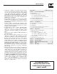
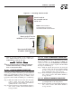
Section 1 — General Information ATS “HS” Type Transfer Switch 1.1 INTRODUCTION Figure 1.1 — Typical ATS Transfer Mechanism This manual has been prepared especially for the purpose of familiarizing personnel with the design, application, installation, operation and servicing of the applicable equipment. Read the manual carefully and comply with all instructions.
Section 2 — Installation GTS “HS” Type Transfer Switch When requesting information or ordering parts for this equipment, make sure to include all information from the DATA DECAL. Record the Model and Serial numbers in the space provided below for future reference. MODEL # SERIAL # 1.4 TRANSFER SWITCH ENCLOSURE The standard switch enclosure is a National Electrical Manufacturer’s Association (NEMA) 3R type.
Section 3 — Operation ATS “HS” Type Transfer Switch Conductor sizes must be adequate to handle the maximum current to which they will be subjected to, based on the 75°C column of tables, charts, etc. used to size conductors. The installation must comply fully with all applicable codes, standards and regulations. Before connecting wiring cables to terminals, remove any surface oxides from the cable ends with a wire brush. All power cables must enter the enclosure through the knockouts.
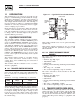
Section 3 — Operation ATS “HS” Type Transfer Switch Figure 3.1 — Actuating Transfer Switch Attach handle to the moveable contact carrier arm. NOTE: Return handle to storage position in enclosure when finished with manual transfer. Move handle UP for the NORMAL (UTILITY) position. Move handle DOWN for the STANDBY (EMERGENCY) position. • Manual operation handle in the DOWN position - LOAD terminals (T1, T2) are connected to EMERGENCY terminals (E1, E2).
Section 3 — Operation ATS “HS” Type Transfer Switch 3.3 VOLTAGE CHECKS 1. Turn ON the UTILITY power supply to the transfer switch using the service disconnect circuit breaker. DANGER WITH CAUTION. THE TRANSFER PROCEED SWITCH IS NOW ELECTRICALLY HOT. CONTACT 2. 3. 4. 5. 6. 7. WITH LIVE TERMINALS RESULTS IN EXTREMELY HAZARDOUS AND POSSIBLY FATAL ELECTRICAL SHOCK. With an accurate AC voltmeter, check for correct voltage. Measure across ATS terminal lugs N1 and N2.
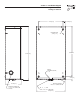
Section 4 — Installation Diagram ATS “HS” Type Transfer Switch Drawing No. 0F0016-B 271mm[10.67"] 0A6599tv MOUNTING HOLES Ø6.3mm[Ø0.25"] 26.5mm[1.04"] 0A6599tv 561mm[22.09" 597mm[23.50"] PADLOCK (CUSTOMER SUPPLIED) LOCATION 0A 34mm[1.34"] 179.5mm[7.07"] KNOCKOUT SUITABLE FOR 1", 1-1/4", 1-1/2" CONDUIT SIZE 3 PLACES KNOCKOUT SUITABLE FOR 3/4" & 1" CONDUIT SIZE KNOCKOUT SUITABLE FOR 1", 1-1/4", 1-1/2" CONDUIT SIZE 324mm[12.
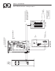
UTILITY METER SOCKET 8 E2 T2 44 11 33 22 AC GENERATOR CONTROL PANEL E1 GROUND BAR E1 194 N1 N2 *-WIRES T1 & T2 NOT USED ON AIR COOLED UNITS AND SOME LIQUID COOLED UNITS FROM ALTERNATOR STATOR SERVICE DISCONNECT ATS IF ATS IS USED AS SERVICE ENTRANCE DEVICE A BONDING JUMPER WILL NEED TO BE INSTALLED SIZED TO MEET NATIONAL & LOCAL CODES.
Section 5 — Electrical Data ATS “HS” Type Transfer Switch Transfer Switch Interconnections - Drawing No. 0F0017-A IF ATS IS USED AS SERVICE ENTRANCE DEVICE A BONDING JUMPER WILL NEED TO BE INSTALLED SIZED TO MEET NATIONAL & LOCAL CODES. UTILITY METER SOCKET SERVICE DISCONNECT ATS INSULATED SPLICING CONNECTOR OR (NEW WIRES CAN BE PULLED FROM ATS & PANELBOARD). E2 T2 NOTE: INSTALLATION TO BE DONE BY A LICENSED ELECTRICIAN AND MUST MEET ALL NATIONAL, STATE AND LOCAL ELECTRICAL CODES.
Section 5 — Electrical Data ATS “HS” Type Transfer Switch Wiring Diagram/Schematic - Drawing No.
Section 5 — Electrical Data ATS “HS” Type Transfer Switch Wiring Diagram/Schematic - Drawing No.
22473-S 1-4X20STL 22473-S 1-4X20STL 22473-S 1-4X20STL 22473-S 1-4X20STL 22097-S 1/4 STL 22097-S 1/4 STL WAUKESHA, WI. GENERAC POWER SYSTEMS, INC.
Section 6 — Exploded Views and Parts List ATS “HS” Type Transfer Switch 100A Transfer Switch Assembly – Drawing No. 0F0466$-D ITEM PART NO.
Section 6 — Exploded Views and Parts List ATS “HS” Type Transfer Switch 200A Transfer Switch Assembly – Drawing No. 0E9801$-F 16 55 15 31 2 3 52 53 INSIDE RIGHT SIDE 17 0F2712 SERIAL NUMBER MODEL NUMBER SYSTEM VOLTAGE WAUKESHA, WI. GENERAC POWER SYSTEMS, INC.
Section 6 — Exploded Views and Parts List ATS “HS” Type Transfer Switch 200A Transfer Switch Assembly – Drawing No. 0E9801$-F ITEM 1 2 3 4 5 6 7 8 9 10 11 12 13 14 15 16 17 18 19 20 21 22 23 24 25 26 27 28 29 30 31 32 33 34 35 36 37 38 39 40 41 42 * 43 * 44 * 45 * 46 47 48 49 50 51 52 53 54 55 56 PART NO.
Section 7 — Notes ATS “HS” Type Transfer Switch 16 Generac® Power Systems, Inc.
Section 7 — Notes ATS “HS” Type Transfer Switch Generac® Power Systems, Inc.
Section 8 — Warranty ATS “HS” Type Transfer Switch GENERAC POWER SYSTEMS, INC. WARRANTY/SERVICE Generac Power Systems, Inc. will warrant that from the date of purchase, our transfer switch will be free from defects in material and workmanship for the items and periods set forth in the warranty statement found in the owners manual of the Generac Power Systems Inc. generator that this transfer switch will be utilized with.