® POWER SYSTEMS, INC. Owner’s Manual 100 and 200 Amp “V” Type and “Y” Type Transfer Switch Models: 09227-0, 09228-0, 09229-0, and 09230-0 This manual should remain with the unit.
Important Safety Instructions ! ! Read the following information carefully before attempting to install, operate or service this equipment. Also read the instructions and information on tags, decals, and labels that may be affixed to the transfer switch. Replace any decal or label that is no longer legible.
Table of Contents • Because jewelry conducts electricity, wearing it may cause dangerous electrical shock. Remove all jewelry (such as rings, watches, bracelets, etc.) before working on this equipment. • If you must work on this equipment while standing on metal or concrete, place insulative mats over a dry wood platform. Work on this equipment only while standing on such insulative mats. • Never work on this equipment while physically or mentally fatigued.
Section 1 — General Information Generac “V” Type and “Y” Type Transfer Switch 1.1 INTRODUCTION This manual has been prepared especially for the purpose of familiarizing personnel with the design, application, installation, operation and servicing of the applicable equipment. Read the manual carefully and comply with all instructions. This will help to prevent accidents or damage to equipment that might otherwise be caused by carelessness, incorrect application, or improper procedures.
Section 2 — Installation Generac “V” Type and “Y” Type Transfer Switch 2.1 INTRODUCTION TO INSTALLATION This equipment has been wired and tested at the factory. Installing the switch includes the following procedures: • • • • • Mounting the enclosure. Connecting power source and load leads. Connecting the generator start circuit. Installing/connecting any options and accessories. Testing functions. 2.2 UNPACKING Carefully unpack the transfer switch.
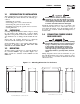
Section 2 — Installation Generac “V” Type and “Y” Type Transfer Switch 2.4.1 2-POLE MECHANISMS Figure 2.4 — 3-Pole Transfer Mechanism These switches (Figures 2.2 and 2.3) are used with a single phase system, when the single phase NEUTRAL line is to be connected to a Neutral Lug and is not to be switched. Figure 2.2 — 100 Amp 2-pole Transfer Mechanism Solderless, screw-type terminal lugs are standard.
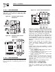
Section 2 — Installation Generac “V” Type and “Y” Type Transfer Switch Figure 2.5 — Transfer Switch Interconnections (Drawing #79963-B) 00 UTILITY SUPPLY NEUTRAL CONNECTION N3, E3 AND T3 NOT USED ON SINGLE PHASE SYSTEMS E1 E2 23 N1 N2 N3 CB2 E3 NEUTRAL LUG 194 UTILITY 1 UTILITY 2 LOAD 1 LOAD 2 TRANSFER SWITCH UTILITY 1 UTILITY 2 E1 E2 E3 LOAD 2 NOTE: 23 POWER LEADS AND TRANSFER SWITCH LEADS MUST BE RUN IN TWO DIFFERENT CONDUITS.
Section 3 — Operation Generac “V” Type and “Y” Type Transfer Switch 3.1 FUNCTIONAL TESTS AND ADJUSTMENTS Following transfer switch installation and interconnection, inspect the entire installation carefully. A competent, qualified electrician should make the inspection. The installation should comply strictly with all applicable codes, standards, laws and regulations. All electrical connections must be correct and in compliance with applicable codes and standards.
Section 3 — Operation Generac “V” Type and “Y” Type Transfer Switch ◆ 3.3.1 “Y” TYPE TRANSFER SWITCHES 3.4 A manual handle was shipped with the transfer switch. Test manual operation for “Y” type transfer switches as follows (Figure 3.2): 1. Turn ON the UTILITY power supply to the transfer switch with whatever means provided (such as the UTILITY maim line circuit breaker). 1. Check that the generator's Auto/Off/Manual switch has been set to OFF position. 2.
Section 3 — Operation Generac “V” Type and “Y” Type Transfer Switch 3.5 GENERATOR TESTS UNDER LOAD 1. Set the generator's main circuit breaker to its OFF or OPEN position. 2. Manually actuate the transfer switch main contacts to their STANDBY position. 3. To start the generator, set the Auto/Off/Manual switch to MANUAL. When engine starts, let it stabilize for a few minutes. 4. Turn the generator's main circuit breaker to its ON or CLOSED position. The generator now powers all LOAD circuits.
Section 4 — Notes Generac “V” Type and “Y” Type Transfer Switch Generac® Power Systems, Inc.
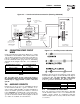
10 Generac® Power Systems, Inc. TRANSFER SWITCH SWITCH TYPE, SPST ELECTRICAL RATINGS, 2A @ 250Vac MIN. - OPEN SWITCH TO TEST - REMOTE TEST SWITCH (OPTIONAL) UTILITY 1 UTILITY 2 LOAD 1 LOAD 2 CUSTOMER LOAD T1 T T2 E1 E E2 N1 N2 UTILITY SUPPLY NEUTRAL LUG POWER LEADS AND TRANSFER SWITCH LEADS MUST BE RUN IN TWO DIFFERENT CONDUITS.
TR 9 A2 LS2 B2 C RED 3 N1 E2 N2 TS - TERMINAL STRIP (CUSTOMER CONNECTION) TR - RELAY, TRANSFER LS1,LS2,LS3 - LIMIT SWITCHES, ACTUATOR 1 7 5 GTS TR 2 T2 GTS - TRANSFER SWITCH CONTACTOR E1 T1 LEGEND WHITE LS3 LS1 B1 C - CONTACTOR ACTUATING COIL E1 6 205 A1 1 4 N1 6 A TR B N2 194 23 N2 NOTE: ALL CONTACTS SHOWN WITH TRANSFER SWITCH IN UTILITY POSITION.
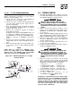
TR 9 A2 LS2 B2 C RED T1 2 T2 7 E1 TR LEGEND WHITE LS3 LS1 B1 1 3 N1 5 E2 N2 GTS 1 N1 C - CONTACTOR ACTUATING COIL GTS - TRANSFER SWITCH CONTACTOR LS1,LS2,LS3 - LIMIT SWITCHES, ACTUATOR PM - POWER MONITOR, 3 PHASE UTILITY TR - RELAY, TRANSFER TS - TERMINAL STRIP (CUSTOMER CONNECTION) E1 6 205 A1 126 PM 4 N1A 6 N2 A TR B N2 N1 23 5 3 N2 N2 194 23 PM T1 T2 NOTE: ALL CONTACTS SHOWN WITH TRANSFER SWITCH IN UTILITY POSITION.
194 23 A TR B NOTE: ALL CONTACTS SHOWN WITH TRANSFER SWITCH IN UTILITY POSITION.
Section 6 — Exploded Views and Parts Lists Transfer Switch - Drawing No. 078589-H DECAL 13 31 DECAL 14 10 12 26 44 10 11 15 9 1 35 32 33 10 12 2 3 4 37 DECAL 34 38 39 40 41 6 7 42 21 22 16 25 24 5 DECAL 43 3 33 23 19 32 33 17 14 Generac® Power Systems, Inc.
Section 6 — Exploded Views and Parts Lists Transfer Switch - Drawing No. 078589-H ITEM 1 2 3 4 5 6 7 8 9 10 11 12 13 14 15 16 17 18 19 20 21 22 23 24 25 26 27** 28 29** 30** 31 32 33 34 35 36 37 38 39 40 41 42 43 44 PART NO.
Section 6 — Exploded Views and Parts Lists Transfer Switch - Drawing No. 078589-H 48 49 36 33 TO RETAIN COVER 22 23 22 9 11 12 16 21 13 23 A 7 19 3 21 A 8 25 16 DETAIL A-A 20 DECAL 28 (POWER TERMINAL LUG ASSY) A DECAL 35 14 A 15 16 47 24 (BOTTOM POWER TERMINALS) 45 40 34 11 42 43 5 4 6 41 12 31 1 46 32 TERM. STRIP REF. ONLY 44 10 DECAL 39 30 DECAL 26 18 37 DECAL 17 16 Generac® Power Systems, Inc.
Section 6 — Exploded Views and Parts Lists Transfer Switch - Drawing No. 078589-H ITEM PART NO.
Section 7 — Warranty Generac “V” Type and “Y” Type Transfer Switch GENERAC POWER SYSTEMS STANDARD TWO-YEAR LIMITED WARRANTY FOR GENERAC TRANSFER SWITCH SYSTEMS NOTE: ALL UNITS MUST HAVE A START-UP INSPECTION PERFORMED BY AN AUTHORIZED GENERAC DEALER. For a period of 2 (two) years from the date of sale/start date, Generac Power Systems, Inc.