
User's Manual


3
OPERATION AND MAINTENANCE
The operator is responsible for proper and safe use
of the equipment. The manufacturer strongly recom-
mends that the operator read this Owner's Manual
and thoroughly understand all instructions before
using this equipment. The manufacturer also strong-
ly recommends instructing other users to properly
start and operate the unit. This prepares them if they
need to operate the equipment in an emergency.
It is the operator's responsibility to perform all safety
checks, to make sure that all maintenance for safe
operation is performed promptly, and to have the
equipment checked periodically by an Authorized
Service Dealer. Normal maintenance service and
replacement of parts are the responsibility of the
owner/operator and, as such, are not considered
defects in materials or workmanship within the
terms of the warranty. Individual operating habits
and usage contribute to the need for maintenance
service.
Proper maintenance and care of the generator ensures
a minimum number of problems and keeps operating
expenses at a minimum. See an Authorized Service
Dealer for service aids and accessories.
Operating instructions presented in this manual
assume that the standby electric system has been
installed by an Authorized Service Dealer or other
competent, qualified contractor. Installation of this
equipment is not a “do-it-yourself” project.
HOW TO OBTAIN SERVICE
When the generator requires servicing or repairs,
contact an Authorized Service Dealer for assistance.
Service technicians are factory-trained and are capa-
ble of handling all service needs.
When contacting an Authorized Service Dealer about
parts and service, always supply the complete model
number of the unit as given on the front cover of this
manual or on the DATA LABEL affixed to the unit.
INTRODUCTION
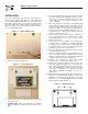
The wireless display system consists of two identical
radio transceivers, one mounted near the generator
and the other (the one with the display), should be
in a convenient viewing location. The system has a
“line of sight” range of about 300 feet but this will be
reduced if the signal has to go through walls, etc.. The
display is intended to show the status of the genera-
tor and warn you if the system is in an alarm state. It
also provides the following additional functions:
Permanent time/date stamped history of generator
events such as starting and stopping
Allowing remote starting and stopping of the gen-
erator
•
•
Facility to set an exercise time & day from the dis-
play
Facility to adjust the “bad” utility voltage thresh-
old
Facility to set up a service schedule
Ability to add extra displays
Graphing capability
The unit can be either battery powered or fed from a
separate plug in wall transformer. The History is kept
in permanent memory that is not lost even when all
power is lost. The clock function is kept alive by a
separate, replaceable 10 year life battery.
BATTERY OPERATION
The wireless display can be operated either from a
plug in wall transformer or from three AAA alkaline
batteries. The batteries can be rechargeable but are
NOT recharged from the wall transformer and should
be separately charged. In the case of battery opera-
tion, the unit will go to sleep for 60 seconds then
exchange data for up to two (2) seconds to conserve
battery life. The display screen will turn off in the
sleep mode unless there is an alarm to be displayed.
It can be awoken by pressing the ENTER key after
which it will remain awake for one (1) minute if no
further keys are pressed. If the display is operated
continuously on batteries, the expected battery life is
three (3) months when using standard alkaline 1.2Ah
batteries. The batteries are NOT used to retain data
such as the history log or the radio settings, they will
not be lost in the event of a dead battery.
NOTE 1:
In battery sleep mode it will take up to two (2)
minutes to detect if the radio link is lost. This long
delay is to allow for the unit’s sleep time.
NOTE 2:
In battery sleep mode, if the wall transformer is
plugged into the unit, it will take up to one minute
to recognize this fact.
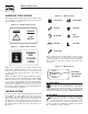
There is a separate battery for the time and date
function. This has an expected life of ten years
after which it can be replaced. To replace the bat-
tery, remove the four screws holding on the back
of the case and carefully fold out the circuit board
without disconnecting the display. Remove the large
yellow battery module from the centre of the board
by pulling on the corners. Replace the battery THE
CORRECT WAY ROUND with the spot in the corner
of the battery facing the on/off switch. Replace the cir-
cuit board and the back of the case. You will need to
reset the time and date. The GENERAC part number
for the battery is 0A7287G.
•
•
•
•
•
Wireless Display System