
User Manual


10
3. On the display select “Reset Radio”. The display will show it
is searching for the generator, this process will last up to one
(1) minute and a countdown timer will be displayed.
4. Once the time is up a message will be displayed showing
that the generator has been found. The radio settings will be
remembered for the next time.
5. Re-set the exercise time.
ADD NEW DISPLAY
An extra remote display can be added to the network. Each display
needs to be trained as to what it’s network consists of. This is the
function of the “Add New Display” selection.
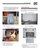
1. Locate the new display near the main display and turn it on.
2. On the NEW display, go to the “Settings” menu and select
“Add me to Network”.
3. Choose a unique address for the additional display, for exam-
ple one that does not conflict with any other additional dis-
plays. If there are only two displays, then any number (other
than zero), will do. Zero is used to cancel the command.
4. On the MAIN display go to the radio menu and select “Add
New Display”. Press enter on both displays. A countdown
timer will be displayed as the two units re-train.
5. At the end of the period, the new display will show that the
training was successful.
TEST RADIO LINK
This feature allows the “basic” data integrity of the link to be
tested, it may not be necessary to use this feature. For ease of
use, the display will NOT revert to the status/alarm screen after
one minute if no keys are pressed.
Test data is sent over the link to the generator end, and then sent
back from the generator end to the display. The data received is
displayed on the bottom line of the display. Good data is shown
as a series of forward slashes (//////). Time-outs on the link are
displayed as the “#” character and corrupted data reply mes-
sages are shown as the “@” character. The messages are termed
“basic” because they are not error checked or corrected.
Radio information such as channel number and quality are also
shown alongside the test data.
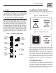
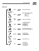
TIME & DATE MENU
Time
There is a live, updating display of the current time, day,
and date shown on the menu icon page (Figure 17).
Figure 17 — Time & Date Menu
MENU
TIME
AND
DATE
04/17/07
Monday
15:25:03
Time
Selecting this menu permits setting the clock to the correct time,
day and date. This will only need to be done the first time the base
station is powered up, or to correct any small errors in the time.
Use the two arrow keys to set the correct time, day and date.
The separate clock in the generator is synchronized to this clock
when it is changed. Synchronization is checked and corrected, if
necessary, every ten minutes. If the clock or date is changed at the
generator, the clock at the base station is also changed automati-
cally (The two clocks are linked together and can be changed at
either end of the link).
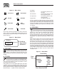
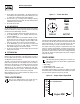
GRAPH MENU
t
The Graph menu permits graphing data in real time on a
rolling screen (Figure 18). Choose what to graph from the
following list:
Utility Voltage•
Generator Battery Volts•
Generator RPM (in units of RPM x 100)•
The display is updated with a new point every 200ms so it takes
about 25 seconds to scroll the whole screen. However new data is
only read from the generator every two (2) seconds.
Figure 18 — Sample Graph of Engine RPM
36
30
24
18
Engine RPM
t
Wireless Display System