diagnostic repair manual Air-Cooled Product MODELS: 7 kW NG, 8 9 kW NG, 10 13 kW NG, 14 16 kW NG, 17 18 kW NG, 20 kW kW kW kW kW LP LP LP LP LP automatic standby generators
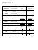
Electrical formulas TO FIND KNOWN VALUES 1-PHASE 3-PHASE KILOWATTS (kW) Volts, Current, Power Factor ExI 1000 E x I x 1.73 x PF 1000 KVA Volts, Current ExI 1000 E x I x 1.73 1000 AMPERES kW, Volts, Power Factor kW x 1000 E kW x 1000 E x 1.73 x PF WATTS Volts, Amps, Power Factor Volts x Amps E x I x 1.73 x PF NO. OF ROTOR POLES Frequency, RPM 2 x 60 x Frequency RPM 2 x 60 x Frequency RPM FREQUENCY RPM, No. of Rotor Poles RPM x Poles 2 x 60 RPM x Poles 2 x 60 RPM Frequency, No.
Contents Specifications........................................................... 4 Generator................................................................. 4 Engine...................................................................... 5 Fuel Consumption.................................................... 5 Mounting Dimensions............................................... 6 Mounting Dimensions............................................... 7 Major Features...............................................
Test 7 – Testing The Stator With A Vom (12-20 kW)...........................................44 Test 8 – Test Brushless Stator..........................45 Test 9 – Check Capacitor..................................46 Test 10 – Test DPE Winding on Brushless units.....................................47 Test 11 – Resistance Check Of Rotor Circuit (12-20 kW)...........................................48 Test 12 – Check Brushes And Slip Rings (12-20 kW)...........................................
PART 4 - DC CONTROL.......................................... 95 4.1 Description and Components........................... 96 General.............................................................96 Terminal Strip / Interconnection Terminal..........96 Circuit Board.....................................................96 Auto-Off-Manual Switch....................................96 7.5 Amp Fuse...................................................96 Menu System Navigation................................102 4.
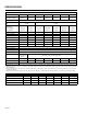
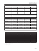
Specifications Generator Unit Rated Max. Continuous Power Capacity (Watts*) 8 kW 10 kW 12 kW 14 kW 16 kW 17 kW 20 kW 7,000 NG 8,000 LP 9,000 NG 10,000 LP 12,000 NG 12,000 LP 13,000 NG 14,000 LP 16,000 NG 16,000 LP 16,000 NG 17,000 LP 18,000 NG 20,000 LP Rated Voltage 120/240 Rated Voltage at No-Load (NG) 220-235 247-249 Rated Max. Continuous Load Current (Amps) 120 Volts** (NG/LP) 240 Volts (NG/LP) 58.3/66.6 29.2/33.3 75.0/83.3 37.5/41.6 100.0/100.0 50.0/50.0 108.3/116.6 54.2/58.
Specifications Engine Model 8 kW 10 kW 12/14/16/17 kW 20 kW Type of Engine GH-410 GT-530 GT-990 GT-999 1 2 2 2 Rated Horsepower @ 3,600 rpm 14.8 18 32 34 Displacement 407cc 530cc 992cc 999cc Number of Cylinders Cylinder Block Aluminum w/Cast Iron Sleeve Valve Arrangement Overhead Valves Ignition System Recommended Spark Plug Spark Plug Gap Compression Ratio Solid-state w/Magneto RC14YC BPR6HS RC14YCA RC12YC 0.76 mm (0.030 inch) 0.76 mm (0.030 inch) 1.02 mm (0.
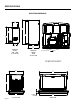
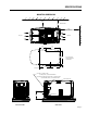
Specifications Mounting Dimensions 299 [11.8] 1079.5 [42.5] 698 [27.5] 997 [39.3] 747 [29.4] 207 [8.2] 454 [17.9] 508 [20.0] TRANSFER SWITCH 8KW - 17KW (IF SUPPLIED) TRANSFER SWITCH 20KW (IF SUPPLIED) Ø30.2 [Ø1.2] LIFTING HOLES 4 CORNERS "DO NOT LIFT BY ROOF" 637.6 [25.1] 1218 [47.9] 731.9 [28.8] 642 [25.3] LEFT SIDE VIEW Page 6 76.2 [3.0] PEA GRAVEL MINIMUM 1226 [48.
Specifications Mounting Dimensions AIR INTAKE 457.2 [18.0] MINIMUM DISTANCE 914 [36.0] MINIMUM OPEN AREA ON SIDES AND FRONT AIR OUTLET AIR INTAKE 250.0 [9.8] 575.3 [22.7] 530.0 [20.9] 446.6 [17.6] 378.7 [14.9] HOLE LOCATIONS FOR OPTIONAL MOUNTING TO A CONCRETE PAD 44.8 [1.8] FRONT OF UNIT FUEL INLET - 12-20KW (1/2" NPT) 8 & 10KW (3/4" NPT) - USE SUPPLIED ADAPTER REQUIRED FUEL PRESSURE: NATURAL GAS = 5-7" WATER COLUMN LIQUID PROPANE (VAPOR) = 10-12" WATER COLUMN CABLE ACCESS HOLE 244.4 [9.
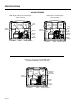
Specifications Major Features 8kW, Single Cylinder, GH-410 Engine (door removed) Oil Dipstick Data Label (see sample) 10kW, V-twin, GT-530 Engine (door removed) Circuit Breaker Control Panel Exhaust Enclosure Oil Dipstick Data Label (see sample) Control Panel Circuit Breaker Exhaust Enclosure Air Filter Air Filter Fuel Inlet (back) Fuel Inlet (back) Fuel Regulator Composite Base Oil Filter Fuel Regulator Battery Compartment Composite Base Oil Filter Figure 1.
Table of contents PART 1 GENERAL INFORMATION Part Title Page 1.1 Generator Identification 10 1.2 Installation Basics 11 1.3 Non-Prepackaged 14 Interconnections 1.3 Preparation Before Use 16 1.4 Testing, Cleaning and Drying 18 1.5 Engine-Generator Protective 25 Devices 1.6 Operating Instructions 27 1.7 Automatic Operating 29 Parameters Air-cooled, Automatic Standby Generators 1.1 Generator Identification.................................... 10 Introduction........................
Section 1.1 Part 1 Generator Identification General information It is not our intent to provide detailed disassembly and reassemble instructions in this manual. It is our intent to (a) provide the service technician with an understanding of how the various assemblies and systems work, (b) assist the technician in finding the cause of malfunctions, and (c) effect the expeditious repair of the equipment.
General information Section 1.2 Part 1 Introduction Information in this section is provided so that the service technician will have a basic knowledge of installation requirements for home standby systems. Problems that arise are often related to poor or unauthorized installation practices. A typical home standby electric system is shown in Figure 1 (next page). Installation of such a system includes the following: • Selecting a Location • Grounding the generator. • Providing a fuel supply.
Section 1.2 Part 1 Installation basics Figure 1.
General information Section 1.2 Part 1 Installation basics Power Source And Load Lines System Control Interconnections The utility power supply lines, the standby (generator) supply lines, and electrical load lines must all be connected to the proper terminal lugs in the transfer switch. The following rules apply: In 1-phase systems with a 2-pole transfer switch, connect the two utility source hot lines to Transfer Switch Terminal Lugs N1 and N2.
Section 1.3 Part 1 Non-Prepackaged Interconnections Discussion: On the current model air-cooled generators Wire 194 was changed to 15B. Wire 15B is still utilized for positive voltage for the transfer relay and Wire 23 is still the control ground for transferring the generator. By following the procedures below it is possible to connect new product with Wire 15B to old or current product that still utilize Wire 194, such as an RTS switch. 3.
General information Section 1.3 Part 1 Non-Prepackaged Interconnections Connect a 2008 and later load center switch to a Pre-2008 air-cooled generator. CONTROL WIRES FROM ENGINE GENERATOR Procedure: 1. Follow all instructions located in the Installation Manual that was supplied with the unit regarding mounting of the switch, junction box, and generator. Note: When installing a standalone pre-2008 generator, the battery charger will be located in the generator utilizing the 12 VDC trickle charger. 2.
Section 1.4 Part 1 Preparation Before Use General The installer must ensure that the home standby generator has been properly installed. The system must be inspected carefully following installation. All applicable codes, standards and regulations pertaining to such installations must be strictly complied with. In addition, regulations established by the Occupational Safety and Health Administration (OSHA) must be complied with.
General information Section 1.4 Part 1 in the selector knob and pull out to overcome spring pressure and then twist clockwise 90 degrees and allow the selector to return in once aligned with the LP (Liquid Propane) position. 6. Save this tool with the Owner's Manual. 7. Install the battery, door and close the roof. 8. Reverse the procedure to convert back to natural gas. Preparation before use FUEL SELECTION LEVER “OUT” POSITION FOR LIQUID PROPANE (VAPOR) FUEL Figure 3.
Section 1.4 Part 1 Preparation before use General information Engine Oil Recommendations FUEL SELECTION LEVER “OUT” POSITION FOR LIQUID PROPANE (VAPOR) FUEL All oil should meet minimum American Petroleum Institute (API) Service Class SJ, SL or better. Use no special additives. Select the oil's viscosity grade according to the expected operating temperature.
General information Section 1.5 Part 1 Testing, Cleaning And Drying Meters Measuring AC Voltage Devices used to measure electrical properties are called meters. Meters are available that allow one to measure (a) AC voltage, (b) DC voltage, (c) AC frequency, and (d) resistance In ohms. The following apply: • To measure AC voltage, use an AC voltmeter. • To measure DC voltage, use a DC voltmeter. • Use a frequency meter to measure AC frequency In “Hertz” or “cycles per second”.
Section 1.5 Part 1 Testing, cleaning and drying Measuring Current Clamp-On: To read the current flow, in AMPERES, a clamp-on ammeter may be used. This type of meter indicates current flow through a conductor by measuring the strength of the magnetic field around that conductor. The meter consists essentially of a current transformer with a split core and a rectifier type instrument connected to the secondary.
General information Section 1.5 Part 1 Testing, cleaning and drying Component testing may require a specific resistance value or a test for INFINITY or CONTINUITY. Infinity is an OPEN condition between two electrical points, which would read as no resistance on a VOM. Continuity is a closed condition between two electrical points, which would be indicated as very low resistance or “ZERO” on a VOM. Electrical Units Ampere: The rate of electron flow in a circuit is represented by the AMPERE.
Section 1.5 Part 1 Testing, cleaning and drying Visual Inspection When it becomes necessary to test or troubleshoot a generator, it is a good practice to complete a thorough visual inspection. Remove the access covers and look closely for any obvious problems. Look for the following: • Burned or broken wires, broken wire connectors, damaged mounting brackets, etc. • Loose or frayed wiring insulation, loose or dirty connections. • Check that all wiring is well clear of rotating parts.
General information Section 1.5 Part 1 Hi-pot Tester: A “Hi-Pot” tester is shown in Figure 7. The model shown is only one of many that are commercially available. The tester shown is equipped with a voltage selector switch that permits the power supply voltage to be selected. It also mounts a breakdown lamp that will illuminate to indicate an insulation breakdown during the test.
Section 1.5 Part 1 Testing, cleaning and drying Testing All Stator Windings To Ground: 1. Disconnect Stator Output Leads 11 and 44 from the generator main line circuit breaker. 2. Disconnect Stator Output Leads 2 and 6 from the capacitor located on the end of the stator assembly. 3. Remove Stator Output Leads 22 and 33 from the neutral connection and separate the two leads. 4. Connect the terminal ends of Wires 11, 22, 33, and 44 together.
General information Part 1 Section 1.6 Engine-generator Protective Devices General Overspeed Shutdown Standby electric power generators will often run unattended for long periods of time. Such operating parameters as (a) battery voltage, (b) engine oil pressure, (c) engine temperature, (d) engine operating speed, and (e) engine cranking and startup are not monitored by an operator during automatic operation.
Section 1.6 Engine-generator protective devices Overcrank Shutdown This feature prevents the generator from damaging itself when it continually attempts to start and another problem, such as no fuel supply, prevents it from starting. The unit will crank and rest for a preset time limit. Then, it will stop cranking, and the LCD screen or the LED on the generator control panel will light indicating an overcrank failure.
General information Section 1.7 Part 1 Operating Instructions Control Panel * DANGER: WHEN THE GENERATOR IS INSTALLED IN CONJUNCTION WITH AN AUTOMATIC TRANSFER SWITCH, ENGINE CRANKING AND STARTUP CAN OCCUR AT ANY TIME WITHOUT WARNING (PROVIDING THE AUTO-OFF-MANUAL SWITCH IS SET TO AUTO). TO PREVENT AUTOMATIC STARTUP AND POSSIBLE INJURY THAT MIGHT BE CAUSED BY SUCH STARTUP, ALWAYS SET THE AUTO-OFF-MANUAL SWITCH TO ITS OFF POSITION BEFORE WORKING ON OR AROUND THIS EQUIPMENT.
Section 1.7 Operating instructions 10-20 KW – INSTALLATION ASSISTANT: Upon first power up of the generator, the display interface will begin an installation assistant. The assistant will prompt the user to set the minimum settings to operate. These settings are simply: Current Date/Time and Exercise Day/Time. The maintenance intervals will be initialized when the exercise time is entered for the first time (Figure 3.2).
General information Part 1 Introduction When the generator is installed in conjunction with a transfer switch, either manual or automatic operation is possible. Manual transfer and engine startup, as well as manual shutdown and re-transfer are covered in Section 1.7. Selection of fully automatic operation is also discussed in that section. This section will provide a step-by-step description of the sequence of events that will occur during automatic operation of the system.
Section 1.8 Automatic operating parameters LOAD TRANSFER The transfer of load when the generator is running is dependent upon the operating mode as follows: 1. Manual • Will not transfer to generator if utility is present. • Will transfer to generator if utility fails (below 65% of nominal for 10 consecutive seconds. • Will transfer back when utility returns for 15 consecutive seconds. The engine will continue to run until removed from the Manual mode. 2.
Table of contents PART 2 AC GENERATORS Part Title Page# 2.1. Description and Components 30 2.2 Operational Analysis 33 2.3 Troubleshooting Flow Charts 35 2.4 Diagnostic Tests 39 Air-cooled, Automatic Standby Generators 2.1 Description and Components........................... 32 Introduction.......................................................32 Engine-Generator Drive System.......................32 The AC Generator.............................................32 Rotor Assembly...........
Section 2.1 Description & components Part 2 Introduction The air-cooled, automatic standby system is an easy to install, fully enclosed and self-sufficient electric power system. It is designed especially for homeowners, but may be used in other applications as well. On occurrence of a utility power failure, this high performance system will (a) crank and start automatically, and (b) automatically transfer electrical loads to generator AC output.
AC generators Section 2.1 Part 2 Description & components Stator Assembly SLIP RINGS The stator can houses and retains (a) dual AC power windings, and (b) excitation winding. A total of six (6) or eight (8) stator leads are brought out of the stator can as shown in Figure 4. The stator can is sandwiched between an engine adapter and a rear bearing carrier. It is retained in that position by four stator studs. 2 BEARING 6 11P Figure 2.
Section 2.1 Description & components Brush Holder And Brushes (12-20 kW) The brush holder is retained to the rear bearing carrier by means of two #10-32 x 9/16 Taptite screws. A positive (+) and a negative (-) brush are retained in the brush holder, with the positive (+) brush riding on the slip ring nearest the rotor bearing. Wire 4 connects to the positive (+) brush and Wire 0 to the negative (-) brush. Wire 0 connects to frame ground.
Section 2.2 Operational analysis Part 2 AC generators Rotor Residual Magnetism The generator revolving field (rotor) may be considered to be a permanent magnet. Some “residual” magnetism is always present in the rotor. This residual magnetism is sufficient to induce a voltage into the stator AC power windings that is approximately 2-12 volts AC. Field boost voltage is reduced from that of battery voltage by the resistor action and, when read with a DC voltmeter, will be approximately 9 or 10 volts DC.
Section 2.2 Operational analysis Operation (8/10 kW) STARTUP: When the engine is started, residual magnetism from the rotor induces a voltage into (a) the stator AC power windings, and (b) the stator excitation or DPE windings. The capacitor on the DPE winding will be charged and then will discharge causing a voltage to be induced back into the rotor. Field Excitation: An AC voltage is induced into the stator excitation (DPE) windings.
Section 2.3 Troubleshooting flowcharts Part 2 AC generators General Use the “Flow Charts” in conjunction with the detailed instructions in Section 2.4. Test numbers used in the flow charts correspond to the numbered tests in Section 2.4. The first step in using the flow charts is to correctly identify the problem. Once that has been done, locate the problem on the following pages. For best results, perform all tests in the exact sequence shown in the flow charts.
Section 2.3 Part 2 Troubleshooting flowcharts AC generators Problem 1 - Generator Produces Zero Voltage or Residual Voltage (12-20 kW Continued) TEST 4 - PERFORM FIXED EXCITATION / ROTOR AMP DRAW E F TEST 7 - TEST STATOR GOOD H TEST 13 TEST ROTOR ASSEMBLY BAD PERFORM STATOR INSULATION RESISTANCE TEST SECTION 1.4 BAD BAD GOOD REPAIR OR REPLACE GOOD PERFORM ROTOR INSULATION RESISTANCE TEST SECTION 1.
Section 2.3 Part 2 AC generators Troubleshooting flowcharts Problem 3 - Generator Produces Low Voltage at No-Load TEST 2 - CHECK AC OUTPUT VOLTAGE LOW SINGLE CYLINDER UNITS TEST 14 - CHECK AC OUTPUT FREQUENCY LOW TEST 16 - CHECK STEPPER MOTOR CONTROL LOW V-TWIN UNITS NO VOLTAGE 12-20 kW UNITS GO TO TEST 4 GO TO “PROBLEM 2” 8/10 kW UNITS TEST 9 CHECK CAPACITOR TEST 15 - ADJUST ENGINE GOVERNOR 8/10 kW UNITS FREQUENCY AND VOLTAGE O.K. FREQUENCY O.K.
Section 2.3 Part 2 Troubleshooting flowcharts AC generators Problem 4 - Voltage and Frequency Drop Excessively When Loads Are Applied TEST 18 - CHECK VOLTAGE AND FREQUENCY UNDER LOAD TEST 19 - CHECK FOR OVERLOAD CONDITION BOTH LOW IF RECONFIGURED TO LP GAS, VERIFY THAT PROPER PROCEDURE WAS FOLLOWED (REFER TO SECTION 1.
AC generators Section 2.4 Diagnostic tests Part 2 Introduction This section is provided to familiarize the service technician with acceptable procedures for the testing and evaluation of various problems that could be encountered on standby generators with air-cooled engine. Use this section of the manual in conjunction with Section 2.3, “Troubleshooting Flow Charts”. The numbered tests in this section correspond with those of Section 2.3.
Section 2.4 Part 2 Diagnostic tests * D ANGER: USE EXTREME CAUTION DURING THIS TEST. THE GENERATOR WILL BE RUNNING. HIGH AND DANGEROUS VOLTAGES WILL BE PRESENT AT THE TEST TERMINALS. CONNECT METER TEST CLAMPS TO THE HIGH VOLTAGE TERMINALS WHILE THE GENERATOR IS SHUT DOWN. STAY CLEAR OF POWER TERMINALS DURING THE TEST. MAKE SURE METER CLAMPS ARE SECURELY ATTACHED AND WILL NOT SHAKE LOOSE. AC generators PROCEDURE: 1. Disconnect Wire 4 from the voltage regulator, 3rd terminal from the top.
Section 2.4 Part 2 Above 2.5A 1.59 - 1.07 1.59 - 1.07 1.39 - 0.93 1.59 - 1.07 1.59 - 1.07 1.39 - 0.93 1.59 - 1.07 1.59 - 1.07 1.39 - 0.93 16 kW 17 kW 20 kW Running Rotor Amp Draw RESULTS: If CONTINUITY was not measured, repair or replace the wire as needed. Static Rotor Amp Draw 3. Connect one test lead to Wire 0, connect the other test lead to a clean frame ground. The meter should read CONTINUITY. Results: 2. Remove Wire 0 from the voltage regulator, 4th terminal from the top.
Section 2.4 Part 2 Diagnostic tests Test 6 – Check Field Boost (12-20 kW) DISCUSSION: See “Field Boost Circuit” in Section 2.2. Field boost current (from the circuit board) is available to the rotor only while the engine is cranking. Loss of field boost output to the rotor may or may not affect power winding AC output voltage. The following facts apply: • A small amount of voltage must be induced into the DPE winding to turn the voltage regulator on.
AC generators Section 2.4 Part 2 Diagnostic tests 5. Turn the Main Breaker to the "ON" or CLOSED position. Test for a short circuit between windings: 6. Set a VOM to measure resistance. 15. Connect one test lead to stator lead Wire 11 on the load side of the main circuit breaker. Connect the other test lead to stator lead Wire 33. 7. Connect one meter test lead to Wire 11 on the load side of the main breaker. Connect the other meter test lead to Wire 22 (power winding).
Section 2.4 Part 2 Diagnostic tests AC generators • An open circuit condition • A “short-to-ground” condition • A short circuit between windings Note: The resistance of stator windings is very low. Some meters will not read such a low resistance, and will simply indicate CONTINUITY. Recommended is a high quality, digital type meter capable of reading very low resistances. Note: Wire 11 and Wire 44 could be switched on the main breaker.
Section 2.4 Part 2 AC generators PROCEDURE: 1. Consult the owner’s manual of the meter being used for directions on measuring capacitance. Figure 7 shows a typical meter and how to check capacitance. 2. Connect the meter leads directly across the terminals of the capacitor. The rated µf (micro farad) of the capacitor is marked on the side of the canister. 3. The meter should display the correct µf reading ± 5µf. If anything other than the indicated rating is displayed, replace the capacitor.
Section 2.4 Diagnostic tests 2. Testing for a “grounded” condition: Any resistance reading indicated the winding is grounded. 3. Testing for a “shorted” condition: Any resistance reading indicated the winding is shorted. 4. If stator tests good and wire continuity tests good, refer back to flow chart. Part 2 AC generators CONTINUITY should be measured. If INFINITY is measured repair or replace Wire 0 between the brush assembly and the voltage regulator.
AC generators Section 2.4 Part 2 RESULTS: 1. Repair, replace or reconnect wires as necessary. 2. Replace any damaged slip rings or brush holder. 3. Clean and polish slip rings as required. Test 13 – Test Rotor Assembly (12-20 kW) DISCUSSION: A rotor having completely open windings will cause loss of excitation current flow and, as a result, generator AC output voltage will drop to “residual” voltage. A “shorted” rotor winding can result in a low voltage condition. PROCEDURE: I.
Section 2.4 Part 2 Diagnostic tests SECONDARY ADJUST SCREW GOVERNOR SHAFT Test 16 – Check Stepper Motor Control (V-twin Engine Units) PROCEDURE: 1. Remove air cleaner cover to access stepper motor. GOVERNOR CLAMP BOLT PRIMARY ADJUST SCREW Figure 10. Engine Governor Adjustment Single Cylinder Engines PROCEDURE (8 kW Units with dual governor springs): 1. Loosen the governor clamp bolt (Figure 10). 2.
AC generators Part 2 STEPPER MOTOR Section 2.4 Diagnostic tests BLACK BROWN YELLOW ORANGE RED EMPTY Figure 14. Six Pin Connector Wire Colors PULL ARM THIS DIRECTION TO CLOSE THROTTLE Figure 11. Throttle Positions 9/10 kW Units STEPPER MOTOR PULL ARM THIS DIRECTION TO CLOSE THROTTLE STEPPER MOTOR ARM Test 17 – Check And Adjust Voltage Regulator (12-20 kW) DISCUSSION: For additional information, refer to description and components Section 2.1.
Section 2.4 Part 2 Diagnostic tests Test 18 – Check Voltage And Frequency Under Load DISCUSSION: It is possible for the generator AC output frequency and voltage to be good at no-load, but they may drop excessively when electrical loads are applied. This condition, in which voltage and frequency drop excessively when loads are applied, can be caused by (a) overloading the generator, (b) loss of engine power, or (c) a shorted condition in the stator windings or in one or more connected loads.
AC generators Section 2.4 Part 2 Diagnostic tests CRIMP ON STANDARD FEMALE BLADE CONNECTORS 4 ft. 12 AWG MOMENTARY PUSHBUTTON ON/OFF SWITCH SINGLE POLE SWITCH ON LIVE SIDE 12 AWG DO NOT SUBSTITUTE ANY OTHER DEVICE STANDARD MALE PLUG Figure 17. Construction of Energizing Cord DEPRESS SWITCH FOR ONE SECOND PLUG ENERGIZING CORD INTO AC OUTLET CAPACITOR WIRES 2 & 6 TO DPE WINDING CAPICITOR REMAINS CONNECTED TO GENERATOR Danger: The capacitor may need to be discharged before testing.
NOTES Page 54
Table of contents PART 3 TRANSFER SWITCH Part Title PG# 3.1. Description and Components 50 3.2 Operational Analysis 54 3.3 Troubleshooting Flow Charts 64 3.4 Diagnostic Tests 66 Air-cooled, Automatic Standby Generators 3.1 Description and Components................................................56 General 5. 5 6 Enclosure............................................................................. 56 Transfer Mechanism.............................................................
Section 3.1 Part 3 Description & components Transfer switch General Enclosure The “W/V-Type” transfer switch is rated 100 amps at 250 volts maximum. It is available in 2-pole configuration only and, for that reason, is usable with 1-phase systems only. Transfer switches do not have an intelligence system of their own. Instead, automatic operation of these transfer switches is controlled by a circuit board housed in the generator control panel.
Transfer switch Transfer Mechanism The 2-pole transfer mechanism consists of a pair of moveable LOAD contacts, a pair of stationary UTILITY contacts, and a pair of stationary STANDBY contacts. The load contacts can be connected to the utility contacts by a utility closing coil; or to the standby contacts by a standby closing coil. In addition, the load contacts can be actuated to either the UTILITY or STANDBY side by means of a manual transfer handle. See Figures 2 and 3. STANDBY Section 3.
Section 3.1 Part 3 Description & components c. When de-energized, the relay’s normally open contacts are open and its normally-closed contacts are closed. d. The normally-closed relay contacts will deliver utility source power to the utility closing circuit of the transfer mechanism. e. The normally open relay contacts will deliver standby source power to the transfer mechanism’s standby closing circuit. 194 A Transfer switch Neutral Lug The standby generator is equipped with an UNGROUNDED neutral.
Transfer switch Section 3.1 Part 3 Description & components TERMINALS 0, 15B and 23: These terminals connect the transfer relay to the generator circuit board. See “Transfer Relay” in Section 3.1. N1A F2 N2A BLACK Fuse Holder The fuse holder holds three (3) fuses, designated as fuses F1, F2 and F3. Each fuse is rated 5 amperes. F3 F1 FUSES F1, F2: These two fuses protect the UTILITY 1 and UTILITY 2 circuit against overload. FUSES F3: This fuse protects the battery charger against overload.
Section 3.2 Part 3 Operational analysis Transfer switch Operational Analysis Figure 1 is a schematic for a typical “W/V-Type” transfer switch.
Section 3.2 Part 3 Transfer switch Operational analysis Figure 2 is a wiring diagram for a typical “W/V-Type” transfer switch.
Section 3.2 Part 3 Operational analysis Transfer switch Utility Source Voltage Available Figure 3 is a schematic representation of the transfer switch with utility source power available. The circuit condition may be briefly described as follows: • Utility source voltage is available to terminal lugs N1 and N2 of the transfer mechanism, transfer switch is in the UTILITY position and source voltage is available to T1, T2 and customer load.
Section 3.2 Part 3 Transfer switch Operational analysis Utility Source Voltage Failure If utility source voltage should drop below a preset value, the generator circuit board will sense the dropout. The circuit board will then initiate generator cranking and startup after a time delay circuit times out. Figure 4 is a schematic representation of the transfer switch with generator power available, waiting to transfer. • Generator voltage available E1, E2.
Section 3.2 Part 3 Operational analysis Transfer switch Transfer To Standby 12 VDC is delivered to the transfer relay via Wire 15B and back to the circuit board via Wire 23. However, circuit board action holds the Wire 23 circuit open and the transfer relay remains de-energized. On generator startup, an “engine warm-up timer” on the generator circuit board starts timing. When that timer has timed out, circuit board action completes the Wire 23 circuit to ground.
Section 3.2 Part 3 Transfer switch Operational analysis Transfer To Standby When the standby coil is energized it pulls the transfer switch mechanism to a overcenter position towards the standby power source side, the transfer switch mechanically snaps to the standby position. On closure of the main contacts to the standby power source side, limit switches SW2 and SW3 are mechanically actuated to “arm” the circuit for re- transfer to utility power source side.
Section 3.2 Part 3 Operational analysis Transfer switch Utility Restored Utility voltage is restored and is available to Terminals N1 and N2. The utility voltage is sensed by the generators circuit board. If it is above a preset value for a preset time interval a transfer back to utility power will occur.
Section 3.2 Part 3 Transfer switch Operational analysis Utility Restored, Transfer Switch De-energized After the preset time interval expires the circuit board will open the Wire 23 circuit to ground. The transfer relay de-energizes, it’s normally closed contacts close, and utility source voltage is delivered to the utility closing coil (C1), via Wires N1A and N2A, closed Transfer Relay Contacts 1 and 7, and Limit Switch SW2.
Section 3.2 Part 3 Operational analysis Transfer switch Utility Restored, Retransfer Back To Utility As the utility coil pulls the transfer switch to an OVER CENTER position, the switch mechanically snaps to Utility. On closure of the main contacts to the utility power source side, Limit Switches SW2 and SW3 are mechanically actuated to “arm” the circuit for transfer to standby.
Section 3.2 Part 3 Transfer switch Operational analysis Transfer Switch In Utility When the transfer switch returns to the utility side, generator shutdown occurs after approximately one (1) minute.
Section 3.3 Part 3 Troubleshooting flow charts Transfer switch Introduction To Troubleshooting The first step in troubleshooting is to correctly identify the problem. Once that is done, the cause of the an be found by performing the tests in the appropriate flow chart. Test numbers assigned in the flow charts are identical to test numbers in Section 3.4, “Diagnostic Tests.” Section 3.4 provides detailed instructions for performance of each test.
Transfer switch Section 3.
Section 3.
Transfer switch Section 3.
Section 3.4 Part 3 Diagnostic tests Transfer switch PROCEDURE: General 1. If the generator engine has started automatically (due to a utility power source outage) and is running, check the position of the generator main circuit breaker. The circuit breaker must be set to its “On” or “Closed” position.
Transfer switch Section 3.4 Part 3 Diagnostic tests e. Set the generator AUTO-OFF-MANUAL switch to AUTO. (1) The generator should crank and start. (2) When the generator starts, an “engine warm-up timer” should start timing. After about 15 seconds, the transfer relay should energize and transfer to the “Standby” source should occur. f. If transfer to “Standby” does NOT occur, check the voltage across transfer switch Terminal Lugs E1 and E2. The generator line-to-line voltage should be indicated.
Section 3.4 Part 3 Diagnostic tests b. Actuate the operating lever down to move the load contacts against the standby contacts, i.e., load connected to the Standby source. 6. Repeat Step 5 several times. As the transfer switch operating lever is moved slight force should be needed until the lever reaches its center position. As the lever moves past its center position, an over-center spring should snap the moveable load contacts against the stationary Standby or Utility contacts. 7.
Transfer switch Section 3.4 Part 3 13. Set VOM to measure DC voltage. 14. Connect the (-) negative meter test lead to Wire 0 at the terminal strip in the generator. Connect the (+) positive meter test lead to Wire 23 at the terminal strip in the generator. 12 VDC should be measured. 15.Place generator AUTO-OFF-MANUAL switch to the AUTO position. Turn off utility power supply to the transfer switch, simulating a utility failure. After the generator starts 10 seconds should elapse before transfer occurs.
Section 3.4 Diagnostic tests 4. Using jumper wires, connect the positive (+) post of a 12 volt battery to relay Terminal “A” and the negative (-) battery post to Relay Terminal “B”. The relay should energize and the VOM should read CONTINUITY. 5. Now, connect the VOM test leads across Relay Terminals 1 and 7. a. Energize the relay and the meter should indicate INFINITY. b. De-energize the relay and the VOM should read CONTINUITY. RESULTS: 1. Replace transfer relay if it is defective. 2.
Section 3.4 Part 3 Diagnostic tests G T2 T1 E2 1 A B 7 9 4 6 1 3 TR1 D E1 E 205 C F SW1 H 1 C2 C1 2 2 SW3 SW2 E1 N1 E2 N2 B A Transfer switch Figure 4.
Section 3.4 Part 3 (2) Press the right arrow key until “Debug” is flashing. (3) Press “Enter”. (4) Press the right arrow key until “Outputs” is flashing. (5) Press “Enter”. (6) Digital Output 8 is Wire 23 output from the board. Refer to Figure 5. (7) If Output 8 shows a “1” then the control board is grounding Wire 23. Replace the printed circuit board. c. If 0 VDC is measured, the Wire 23 circuit is good. Refer to flow chart.
Section 3.4 Part 3 Diagnostic tests T1 2 B E2 SW2 1 B B B F2 F1 F3 A A D N1A E F A A B 7 9 4 6 1 3 TR1 N1A 126 G C I SW1 N2A 1 C2 C1 2 SW3 E1 N1 H A T2 B N2 N2A A Transfer switch Figure 7.
Section 3.4 Part 3 Diagnostic tests 5. Remove Wire N2A from the utility coil C1. Transfer switch TEST 33 – TEST LIMIT SWITCH SW2 and SW3 6. Turn on utility power supply to the transfer switch. a. If transfer to utility occurs, Wire 23 is grounded. Proceed to Test 31. b. If transfer to utility does not occur, proceed to Step 7. 7. Measure across points A and B. 240 VAC should be measured. DISCUSSION: The limit switches are wired to the normally closed contacts.
Transfer switch Section 3.4 Part 3 Diagnostic tests PROCEDURE: 1. On the generator panel, set the AUTO-OFF-MANUAL switch to OFF. 2. Turn off the utility power supply to the transfer switch, using whatever means provided. 3. Remove fuses F1 and F2 from the fuse holder (see Figure 8). 4. Inspect and test fuses for blown condition. With a VOM set to measure resistance, CONTINUITY should be measured across the fuse. N1A F2 N2A BLACK 6.
Section 3.4 Part 3 Diagnostic tests 240 VAC TEST POINTS Transfer switch Procedure: With utility source voltage available to terminal lugs N1 and N2, use a VOM to test for utility source lineto-line voltage across terminal locations N1 and N2 terminals. Normal line-to-line utility source voltage should be indicated. N1A N2A N2 N1 Figure 9.
Section Section x.x 3.
Section 3.4 Diagnostic tests 2. Test for utility source line-to-line voltage across Terminal Lugs N1 and N2 (see Figure 1). Normal utility source voltage should be indicated. RESULTS: 1. If low or no voltage is indicated, find the cause of the problem and correct. 2. If normal utility source voltage is indicated, refer to Flow Chart. Test 40 – CHECK BATTERY CHARGER SUPPLY VOLTAGE “pre-wire load center” DISCUSSION: The battery charger is supplied with 120 VAC. The output of the battery charger is 13.
Transfer switch Part 3 a. If 115 Ohms is measured, proceed to Step 10. b. If zero resistance or CONTINUITY is measured, connect the meter test leads across Terminals A and B on the transfer relay (TR1) c. If zero resistance is measured, a short exists. Replace TR1. d. If 115 Ohms is measured, repair or replace Wire 15B between the generator and the transfer switch. Section 3.
N1 N2 WHITE DETAIL 0 15B 23 GREEN E1 E2 H N1 N2 G DETAIL 0 15B 23 H E1 E2 STANDBY (C2 & VR2) UTILITY (C1 & VR1) N2 N1 C TO GROUNDING ELECTRODE GROUND BC LINE BC 00 T1 T2 E2 T2 E1 T1 N2 N1 CUSTOMER LOAD (DISTRIBUTION PANEL) NEUTRAL BLOCK A RTS TRANSFER SWITCH Diagnostic tests F E D N1 N2 N1 N2 B 23 194 23 15B 5 AMP FUSE Page 88 BC 00 BC LINE G UTILITY SUPPLY FROM SERVICE DISCONNECT Section 3.4 Part 3 Transfer switch Figure 12.
N1 N2 WHITE DETAIL 0 15B 23 GREEN E1 E2 H BC 00 BC LINE G F E DETAIL TO GROUNDING ELECTRODE C H D T1 T2 N1 N2 E2 E1 A B PANELBOARD Part 3 N1 N2 G UTILITY METER SOCKET N1 N2 23 15B SERVICE DISCONNECT ATS 0 15B 23 5 AMP FUSE BC 00 BC LINE Transfer switch Section 3.4 Diagnostic tests Figure 12A. Test 43, 44, and 45 “RTSE Transfer Switch” Test Points.
Section 3.4 Diagnostic tests 6. Measure across points G and H on the terminal strip. 12 VDC should be measured. a. If 12 VDC is measured, proceed to Step 8. b. If 12 VDC is not measured, proceed to Step 7. 7. Measure across point H and ground lug. 12 VDC should be measured. a. If 12 VDC is measured, repair or replace Wire 0 between the generator terminal strip and the ground lug. b. If 12 VDC is not measured, proceed to Step 8. 8. Set VOM to measure resistance. 9.
UTILITY METER SOCKET GEN-READY LOAD CENTER BC-00 BC-LINE A N1 N2 DUPLEX BREAKER E B DETAIL 0 15B 23 F WHITE N1 N2 0 15B 23 GREEN E1 E2 F BC 00 BC LINE ENGINE GENERATOR CONNECTION PANEL DETAIL E D DETAIL C BC 00 BC LINE Part 3 D C DETAIL Transfer switch Section 3.4 Diagnostic tests Figure 13. Test 46, 47, and 48 “GenReady Load Center” Test Points.
Section 3.4 Diagnostic tests 3. Measure across points G and H on the terminal strip. 12VDC should be measured. a. If 12 VDC is measured, the charger should be functioning. b. If 12 VDC is not measured, proceed to Step 4. 4. Remove Wire 0 and Wire 15B from generator terminal strip locations E and F. 5. Wait five (5) minutes after removing wires. Part 3 Transfer switch PROCEDURE: Refer to Figure 14. 1. Set VOM to measure AC voltage. 2. Measure across points A and B. 240 VAC should be measured. a.
23 0 15B G S1 J5 1 2 1 2 J6 LSC D2 2 1 3 2 1 6 5 4 6 5 4 9 8 7 9 8 7 A B H A OUTPUT 3 RED BLK TR D1 LS J1 F3 BC J4 J3 E INPUT F BLK WHT C D WHT BLK 00 (C2) XB1 XA1 NB B A T1 E1 N1 ATS T2 E2 N2 GENERATOR OUTPUT CONNECTION ATS BC C1 C2 C1A C2A F1,F2 F3 GND LS LSC LSS NB TR UCB XA1,XB1 T1 A XB1 XA1 LEGEND B A T2 E2 N2 LSS T1 E1 N1 NON-ESSENTIAL LOAD CONNECTION B TRANSFER SWITCH CONTACTOR BATTERY CHARGER SOLENOID COIL (UTILITY CLOSING) SOLENOID CO
Section 3.4 Diagnostic tests 4. Reconnect battery charger black and red lead wires previously removed in Step 2. 5. Measure across points G and H. 13.4 VDC should be measured. a. If 13.4 VDC is not measured, replace the battery charger. b. If 13.4 VDC is measured, the charger is working. *NOTE: Battery charger voltage will be higher than battery supply voltage.
Table of contents PART 4 DC CONTROL Part Title Page# 4.1. Description and Components 76 4.2 Operational Analysis 82 4.3 Troubleshooting Flow Charts 96 4.4 Diagnostic Tests 103 Air-cooled, Automatic Standby Generators 4.1 Description and Components.....................................96 General. .................................................................... 96 Terminal Strip / Interconnection Terminal.................. 96 Circuit Board...................................................
Section 4.1 Part 4 Description and components DC control General Circuit Board This section will familiarize the reader with the various components that make up the DC control system. Major DC control system components that will be covered include the following: • A Terminal Strip / Interconnection Terminal • A Circuit Board. • An AUTO-OFF-MANUAL Switch. • A 7.5 Amp Fuse.
Section 4.1 Part 4 DC control Description and components 7.5 Amp Fuse This fuse protects the circuit board against excessive current. If the fuse has blown, engine cranking and operation will not be possible. Should fuse replacement become necessary, use only an identical 7.5 amp replacement fuse. Figure 2. A Typical 7.5 Amp Fuse 1 2 1. 2. 3. 5 4 3 TO ENGINE DIVIDER PANEL CONTROL PANEL 7.5 AMP FUSE STARTER CONTACTOR RELAY (10-20 KW) 4. 4 POSITION TERMINAL BLOCK 5. TERMINAL BLOCK 6.
Section 4.1 Part 4 Description and components 18 17 16 15 14 13 12 11 10 4 3 9 8 7 6 5 4 3 2 1 2 1 J2 DC control 18 17 16 15 14 13 12 11 10 4 3 9 2 1 8 J1 7 6 5 4 3 2 1 J2 CONNECTOR (PCB END) J1 CONNECTOR (PCB END) 3 4 10 11 12 13 14 15 16 17 18 1 2 1 2 3 4 5 6 7 8 9 J2 CONNECTOR (HARNESS END) J1 CONNECTOR (HARNESS END) 1 N1/N2 CONNECTOR (PCB END) 2 N1/N2 CONNECTOR (HARNESS END) Figure 4.
Section 4.1 Part 4 DC control 18 17 16 15 14 13 12 11 10 4 3 9 8 7 6 5 4 3 2 1 2 1 J2 Description and components 18 17 16 15 14 13 12 11 10 4 3 9 2 1 8 J1 J3 (STEPPER MOTOR) 7 6 5 4 3 2 1 J2 CONNECTOR (PCB END) J1 CONNECTOR (PCB END) 3 4 10 11 12 13 14 15 16 17 18 1 2 1 2 3 4 5 6 7 8 9 J1 CONNECTOR (HARNESS END) J2 CONNECTOR (HARNESS END) 1 N1/N2 CONNECTOR (PCB END) REMOTE WIRELESS CONNECTION 2 N1/N2 CONNECTOR (HARNESS END) Figure 5.
Section 4.1 Part 4 Description and components 18 17 16 15 14 13 12 11 10 4 3 9 8 7 6 5 4 3 2 1 2 1 J2 DC control 18 17 16 15 14 13 12 11 10 4 3 9 2 1 8 J1 7 6 5 4 3 2 1 J2 CONNECTOR (PCB END) J3 (STEPPER MOTOR) J1 CONNECTOR (PCB END) 3 4 10 11 12 13 14 15 16 17 18 1 2 1 2 3 4 5 6 7 8 9 J1 CONNECTOR (HARNESS END) J2 CONNECTOR (HARNESS END) 1 N1/N2 CONNECTOR (PCB END) Figure 6.
Section 4.1 Part 4 DC control 18 17 16 15 14 13 12 11 10 4 3 9 8 7 6 5 4 3 2 1 2 1 Description and components 18 17 16 15 14 13 12 11 10 9 J2 8 J1 7 6 5 4 2 3 1 J2 CONNECTOR (PCB END) J3 (STEPPER MOTOR) 4 3 2 1 J1 CONNECTOR (PCB END) 3 4 10 11 12 13 14 15 16 17 18 1 2 1 2 3 4 5 6 7 8 9 J1 CONNECTOR (HARNESS END) J2 CONNECTOR (HARNESS END) 1 REMOTE WIRELESS CONNECTION N1/N2 CONNECTOR (PCB END) 2 N1/N2 CONNECTOR (HARNESS END) Figure 7.
Section 4.1 Part 4 Description and components 2 FEMALE SIDE MALE SIDE DC control 1 C3 1 2 Figure 8. Choke Solenoid Connector Pin Number Identification Menu System Navigation To get to the MENU, use the "Esc" key from any page. It may need to be pressed many times before getting to the menu page. The currently selected menu is displayed as a flashing word. Navigate to the menu required by using the +/- keys. When the menu required is flashing, press the ENTER key.
ENTER +/- ESC Use the “ENTER” key to select items or enter data. Use the “+/-” key to navigate through the menu. Press the “ESCAPE” key to jump back up through the menu levels.
Section 4.2 Part 4 Operational analysis DC control Introduction This “Operational Analysis” is intended to familiarize the service technician with the operation of the DC control system on units with air-cooled engine. A thorough understanding of how the system works is essential to sound and logical troubleshooting. The DC control system illustrations on the following pages represent a 14 kW unit. Utility Source Voltage Available See Figure 1, below.
Section 4.2 Part 4 DC control Operational analysis • Utility source voltage is available to transfer switch Terminal Lugs N1/N2. With the transfer switch main contacts at their “Utility” side, this source voltage is available to Terminal Lugs T1/T2 and to the “Load” circuits. • Utility voltage is delivered to the Control Board Wires N1/N2, fuses F1/F2, connected wiring, and Control Panel UTILITY 1 and UTILITY 2 terminals. A voltage of 240 AC is delivered to the circuit board.
Section 4.2 Part 4 Operational analysis DC control Initial Dropout of Utility Source Voltage Refer to Figure 2, below. Should a “Utility” power source failure occur, circuit condition may be briefly described as follows: • The circuit board constantly senses for an acceptable “Utility” source voltage, via transfer switch fuses F1/F2, transfer switch UTILITY 1 and UTILITY 2 terminals, connected wiring, control panel UTILITY 1 and UTILITY 2 terminals, and Wires N1/N2.
Section 4.2 Part 4 DC control Operational analysis • Should utility voltage drop below approximately 65 percent of the nominal source voltage, a programmable timer on the circuit board will turn on. • In Figure 2, the 10-second timer is still timing and engine cranking has not yet begun. • The AUTO-OFF-MANUAL switch is shown in its AUTO position. Battery voltage is available to the circuit board via Wire 13, a 7.5 amp fuse (F1), and Wire 15B. Figure 2.
Section 4.2 Part 4 Operational analysis DC control Utility Voltage Dropout and Engine Cranking • After ten (10) seconds and when the circuit board’s 10-second timer has timed out, if utility voltage is still below 65 percent of nominal, circuit board action will energize the circuit board’s crank and run relays simultaneously. • Printed circuit board action delivers 12 volts DC to a starter contactor relay (SCR), via Wire 56.
Section 4.2 Part 4 DC control Operational analysis • Printed circuit board action delivers 12 volts DC to the fuel solenoids (FS1 & FS2), via Wire 14. The fuel solenoids energize open and fuel is available to the engine. Wire 14 supplies power to the choke solenoid (CS). Circuit board action grounds Wire 90, energizing the choke solenoid cyclically during cranking and continuously while running.
Section 4.2 Part 4 Operational analysis DC control Engine Startup and Running With the fuel solenoids open and ignition occurring, the engine starts. Engine startup and running may be briefly described as follows: • Voltage pulses from the ignition magnetos are delivered to the circuit board via Wire 18. Once the circuit board determines that the engine is running, the circuit board (a) terminates cranking, and (b) terminates the choke solenoid (CS), and (c) turns on an “engine warm-up timer”.
Section 4.2 Part 4 DC control Operational analysis • The “engine warm-up timer” will run for about 5 seconds. When this timer finishes timing, board action will initiate transfer to the STANDBY power source. As shown in Figure 4 (below), the timer is still running and transfer has not yet occurred. • Generator AC output is available to transfer switch Terminal Lugs E1/E2 and to the normally open contacts of a transfer relay. However, the transfer relay is de-energized and its contacts are open.
Section 4.2 Part 4 Operational analysis DC control Initial Transfer to the “Standby” Source The generator is running, the circuit board’s “engine warm-up timer” is timing, and generator AC output is available to transfer switch terminal lugs E1 and E2 and to the open contacts on the transfer relay.
Section 4.2 Part 4 DC control Operational analysis • When the circuit board’s “engine warm-up timer” times out, circuit board action completes the Wire 23 circuit to ground. The transfer relay then energizes and its normally open contacts close. • Standby power is now delivered to the standby closing coil (C2), via Wires E1/E2, the normally open transfer relay contacts, Wire 205, limit switch XB1, Wire B, and a bridge rectifier.
Section 4.2 Part 4 Operational analysis DC control Utility Voltage Restored / Re-transfer to Utility The “Load” is powered by the standby power supply. The circuit board continues to seek an acceptable utility source voltage. On restoration of utility source voltage, the following events will occur: • On restoration of utility source voltage above 75 percent of the nominal rated voltage, a “retransfer time delay” on the circuit board starts timing. The timer will run for about fifteen (15) seconds.
Section 4.2 Part 4 DC control Operational analysis • The utility closing coil (C1) energizes and moves the main current carrying contacts to their NEUTRAL position. The main contacts move to an over center position past NEUTRAL and spring force closes them to their UTILITY side. LOAD terminals are now powered by the UTILITY source. • Movement of the main contacts to UTILITY actuates limit switches XA1/XB1. XA1 opens and XB1 actuates to its STANDBY source side. • The generator continues to run.
Section 4.2 Part 4 Operational analysis DC control Engine Shutdown Following retransfer back to the utility source, an “engine cool-down timer” on the circuit board starts timing. When that timer has timed out (approximately one minute), circuit board action will de-energize the circuit board’s run relay. The following events will then occur: • The DC circuit to Wire 14 and the fuel solenoids (FS1 & FS2) will be opened. The fuel solenoids will deenergize and close to terminate the engine fuel supply.
Section 4.2 Part 4 DC control Operational analysis • Circuit board action will connect the engine’s ignition magnetos (IM1 & IM2) to ground, via Wire 18. Ignition will be terminated. • Without fuel flow and without ignition, the engine will shut down. Figure 7.
Section 4.
Section 4.
Section 4.3 Part 4 Troubleshooting flow charts DC control Problem 18 – Engine Starts Hard and Runs Rough / Lacks Power / Backfires TEST 66 – CHECK FUEL SUPPLY AND PRESSURE IF RECONFIGURED TO LP GAS, VERIFY THAT PROPER PROCEDURE WAS FOLLOWED. (REFER TO SECTION 1.
Section 4.
Section 4.3 Part 4 Troubleshooting flow charts Problem 20 – 7.
DC control Section 4.4 Part 4 Diagnostic tests Introduction Perform these “Diagnostic Tests” in conjunction with the “Troubleshooting Flow Charts” of Section 4.3. The test procedures and methods presented in this section are not exhaustive. The manufacturer could not possibly know of, evaluate and advise the service trade of all conceivable ways in which testing and trouble diagnosis might be performed. The manufacturer has not undertaken any such broad evaluation.
Section 4.4 Part 4 Diagnostic tests DC control Procedure: 1. Simulate a power failure by disconnecting main breaker. 1 DEBUG 2. If the generator does not perform the sequence of events listed in the above discussion, replace the printed circuit board. Results: Refer back to flow chart 2 Test 60 – Check 7.5 Amp Fuse INPUTS DISCUSSION: The 7.5 amp fuse is located on the generator control console.
DC control Section 4.4 Part 4 Diagnostic tests B. Pe r fo r m a l o a d t e s t o n t h e B a t t e r y : (Maintenance Free Battery) b. An average reading of 1.230 means the battery is 75% charged. c. An average reading of 1.200 means the battery is 50% charged. d. An average reading of 1.170 indicates the battery is 25% charged. 1. Using a lead acid battery load tester test the load capability of the battery. 2. Follow the load tester’s manufacturer’s instructions carefully.
Section 4.4 Part 4 Diagnostic tests Test 62 – Check Wire 56 Voltage DISCUSSION: During an automatic start or when starting manually, a crank relay on the circuit board should energize. Each time the crank relay energizes, the circuit board should deliver 12 VDC to a starter contactor relay (SCR), or starter contactor (SC), and the engine should crank.
DC control Section 4.4 Part 4 PROCEDURE: 1. Set a VOM to measure DC voltage. 2. Remove Wire 13 from the Starter Contactor Relay located under the printed circuit board. 3. Connect the positive (+) meter test lead to the Wire 13 connector. Connect the negative (-) meter test lead to a clean frame ground. Battery voltage should be measured. 4. Reconnect Wire 13 to the SCR. 5. Remove Wire 16 from the SCR. Connect the positive (+) meter test lead to the SCR terminal from which Wire 16 was removed.
Section 4.4 Diagnostic tests Part 4 DC control Test 65 – Test Starter Motor Conditions Affecting Starter Motor Performance: 1. A binding or seizing condition in the starter motor bearings. 2. A shorted, open or grounded armature. a. Shorted armature (wire insulation worn and wires touching one another). Will be indicated by low or no RPM. b. Open armature (wire broken) will be indicated by low or no RPM and excessive current draw. c.
DC control Section 4.4 Part 4 Diagnostic tests PINION Figure 13. Check Pinion Gear Operation (Single Cylinder) Figure 15. Tachometer Test Bracket: A starter motor test bracket may be made as shown in Figure 16. A growler or armature tester is available from an automobile diagnostic service supplier. 0.5" TOOLS FOR STARTER PERFORMANCE TEST: The following equipment may be used to complete a performance test of the starter motor: • A clamp-on ammeter. • A tachometer capable of reading up to 10,000 rpm.
Section 4.4 Part 4 Diagnostic tests DC control TENDS TO SETTLE IN HIGH PLACES. LP (PROPANE) GAS IS HEAVIER THAN AIR, AND TENDS TO SETTLE IN LOW AREAS. EVEN THE SLIGHTEST SPARK CAN IGNITE THESE GASES AND CAUSE AN EXPLOSION. STARTER CONTACTOR CLAMP ON AMP METER STARTER MOTOR PROCEDURE: A water manometer or a gauge that is calibrated in “ounces per square inch” may be used to measure the fuel pressure.
DC control Section 4.4 Part 4 Diagnostic tests Procedure: 12-20 kW Units 1. Set the AUTO-OFF-MANUAL switch to OFF. 2. Set a VOM to measure DC voltage. PORT 3 3. Disconnect Wire 14 from the fuel solenoid (FS). PORT 1 PORT 2 Figure 20 (12-20 kW) Gas Pressure Test point 4. Connect the positive test lead to the disconnected Wire 14 from Step 3. Connect the negative test lead to a clean frame ground. 5. Set AUTO-OFF-MANUAL switch to the MANUAL position. The meter should indicate battery voltage. a.
Section 4.4 Diagnostic tests i. Set a VOM to measure resistance. j. Connect one meter test lead to Wire 14 that was disconnected in Step 3. k. Connect the other meter test lead to Wire 14 at J2-3. See Figures on Pages 92-95. l. C O N T I N U I T Y s h o u l d b e m e a s u r e d . I f CONTINUITY is measured, repeat Step 5 and then retest. m. If CONTINUITY is not measured, repair or replace Wire 14 between the J2 Connector and the fuel solenoid. Procedure: 8 kw Units 1. Set AUTO-OFF-MANUAL switch to OFF. 2.
DC control Section 4.4 Part 4 Diagnostic tests 7. With the generator running at a speed of approximately 60 Hertz, verify that the choke is energized and holding the choke plate open. Repeat Step 2 procedure, however, once the unit starts, manually hold the choke open while taking the voltage measurement. CHOKE PLATE CHOKE SOLENOID CHOKE SOLENOID CHOKE PLATE Figure 22. Solenoid De-Energized, Choke Closed 12-20 kW Units CHOKE HOUSING CHOKE PLATE Figure 24.
Section 4.4 Part 4 Diagnostic tests 2. Disconnect the C3 Connector. DC control 2. If Choke Solenoid coil resistance is not measured in Step 8, replace the Choke Solenoid. 3. Set a VOM to measure DC voltage. 4. Connect the positive (+) test lead to Wire 56 (Pin 1) of C3 Connector going to the control panel (Female Side) Connect the negative (-) test lead to Wire 0 (Pin 2). 3. If battery voltage was not measured in Step 4, replace the printed circuit board. 5. Set the AUTO-OFF-MANUAL Switch to MANUAL.
DC control Section 4.4 Part 4 Diagnostic tests CHOKE VALVE IN OPEN POSITION CHOKE SOLENOID AIR BOX CHOKE VALVE IN CLOSED POSITION Figure 26. 8kW Choke Solenoid Figure 28. Checking Ignition Spark Figure 27. Spark Tester To determine if an engine miss is ignition related, connect the spark tester in series with the spark plug wire and the spark plug (Figure 29). Then, crank and start the engine. A spark miss will be readily apparent.
Section 4.4 Part 4 Diagnostic tests DC control NORMAL MISFIRES PRE-IGNITION DETONATION Figure 29. Checking Engine Miss RESULTS: 1. If no spark or very weak spark occurs, go to Test 73. 2. If sparking occurs but engine still won’t start, go to Test 71. 3. When checking for engine miss, if sparking occurs at regular intervals but engine miss continues, go to Test 20. Figure 30. Spark Plug Conditions 4. When checking for engine miss, if a spark miss is readily apparent, go to Test 74.
DC control Section 4.4 Part 4 DISCUSSION: The Cylinder Leak Down Tester checks the sealing (compression) ability of the engine by measuring air leakage from the combustion chamber. Compression loss can present many different symptoms. This test is designed to detect the section of the engine where the fault lies before disassembling the engine. PROCEDURE: 1. Remove a spark plug. 2. Gain access to the flywheel. Remove the valve cover. 3.
Section 4.4 Part 4 Diagnostic tests DC control RESULTS: WIRE 18 CONNECTION 1. If INFINITY was not measured in Step 4, repair or replace shorted ground Wire 18 between the J1 Connector from the circuit board to the stud or bullet connector. 2. If INFINITY was measured in Step 4, replace the circuit board and retest for spark. 3. If ignition spark still has not occurred, proceed to Test 74. Test 74 – Check and Adjust Ignition Magnetos Figure 32. Wire 18 Connection 10-20 kW Units 2.
DC control Section 4.4 Part 4 Procedure, Adjusting Magneto Flywheel Gap: Note: The air gap between the ignition magneto and the flywheel on single cylinder engines is not adjustable. Proceed directly to Step 10 for single cylinder engines. For V-twin engines, proceed as follows. 1. See Figure 34. Rotate the flywheel until the magnet is under the module (armature) laminations. 2. Place a 0.008-0.012 inch (0.20-0.30mm) thickness gauge between the flywheel magnet and the module laminations.
Section 4.4 Diagnostic tests Part 4 DC control RESULTS: If sparking still does not occur after adjusting the armature air gap, testing the ground wires and performing the basic flywheel test, replace the ignition magneto(s). Procedure, Replacing Magnetos: 1. Follow all steps of the Major Disassembly procedures that are located in Section 6. 2. Once the magnetos are visible, make note to how they are connected. Note: Each magneto has its own part number. Verify the part number prior to installation. 3.
DC control Test 75 – Check Oil Pressure Switch And Wire 86 DISCUSSION: If the oil pressure switch contacts have failed in their closed position, the engine will probably crank and start. However, shutdown will then occur within about 5 (five) seconds. If the engine cranks and starts, then shuts down almost immediately with a LOP fault light, the cause may be one or more of the following: • Low engine oil level. • Low oil pressure. • A defective oil pressure switch. PROCEDURE: 1.
Section 4.4 Part 4 Diagnostic tests a. Disconnect the J1 Connector from the printed circuit board. b. Connect one test lead to Wire 86 (disconnected from LOP). Connect the other test lead to Pin Location 4 (Wire 86) of the J1 Connector at the Circuit Board (for all models). CONTINUITY should be measured. If CONTINUITY is not measured, repair or replace Wire 86 between the LOP switch and the J1 Connector. c. Connect one test lead to Wire 0 ( disconnected from LOP).
Section 4.4 Part 4 DC control Diagnostic tests Procedure: (Intake and Exhaust) Make sure that the piston is at Top Dead Center (TDC) of it’s compression stroke (both valves closed). The valve clearance should be 0.05-0.1mm (0.002-0.004 in.) cold. Check and adjust the valve to rocker arm clearance as follows: 1. Remove the four (4) screws from the rocker cover. 2. Remove the rocker cover and rocker cover gasket. 3. Loosen the rocker arm jam nut.
Section 4.4 Part 4 Diagnostic tests 10. Connect one meter test lead to Wire 18 removed from the stud connector. Connect the other meter test lead to a clean frame ground. INFINITY should be measured. If CONTINUITY is measured, repair or replace Wire 18 between the stud connector and the J1 Connector. Results: Refer to flow chart. Procedure: (Single Cylinder) 1. Set a VOM to measure resistance. DC control 3. Press the right arrow key till a line is present under “EDIT”. 4. Press “Enter”. 5.
DC control Part 4 Procedure: 1. Set a VOM to measure resistance. 2. Disconnect the J2 Connector from the controller. 3. Connect one meter test lead to the ground terminal. Connect the other meter test lead to each of the following J2 connector pin locations. J2-11 Wire 56 8kW If CONTINUITY was measured, go to Step 4. Average nominal resistance reading is 4 ohms: Single Cylinder Starter Contactor (SC) 4 ohms, Choke Solenoid (CS) is 4 ohms. 10 kW - 20 kW If CONTINUITY was measured, go to Step 5.
Section 4.4 Part 4 Diagnostic tests d. If coil resistance was measured in CS and FS, and FS2 Wire 14 is shorted to ground between J2 connector and CS, FS, or FS2, repair or replace the shorted wire. 8. Disconnect Wire 14 from the Fuel Solenoid (FS) and Choke Solenoid (CS). a. Connect one meter test lead to the FS terminal from which Wire 14 was removed. Connect the other meter test lead to the ground terminal. 16 ohms should be measured. If zero resistance was measured, replace the FS. b.
Table of contents Part Title 5.1. System Functional Tests PART 5 OPERATIONAL TESTS Air-cooled, Automatic Standby Generators 5.1 System Functional Tests................................. 148 Introduction.....................................................148 Manual Transfer Switch Operation..................148 Electrical Checks............................................148 Generator Tests Under Load...........................149 Checking Automatic Operation.......................
Section 5.1 System functional tests Introduction Following home standby electric system installation and periodically thereafter, the system should be tested Functional tests of the system include the following: • Manual transfer switch operation. • System voltage tests. • Generator Tests Under Load. • Testing automatic operation. Before proceeding with functional tests, read instructions and information on tags or decals affixed to the generator and transfer switch.
Operational tests and adjustments DANGER + Section 5.1 Part 5 The transfer switch is now electrically “hot”, Contact with “hot” parts will result in extremely hazardous and possibly fatal electrical shock. Proceed with caution. 5. Use an accurate AC voltmeter to check utility power source voltage across transfer switch Terminals N1 and N2. Nominal line-to-line voltage should be 240 volts AC. 6.
Section 5.1 System functional tests Part 5 Operational tests and adjustments 11. Let the generator run at full rated load for 20-30 minutes. Listen for unusual noises, vibration or other indications of abnormal operation. Check for oil leaks, evidence of overheating, etc. the unit runs for approximately 12 minutes and then shuts down. Transfer of loads to the generator output does not occur during the exercise cycle unless utility power is lost. 12.
Table of contents Part Title 6.1. Major Disassembly PART 6 DISASSEMBLY Air-cooled, Automatic Standby Generators 6.1 Major Disassembly......................................... 152 Front Engine Access.......................................152 Major Disassembly..........................................156 Torque Requirements (Unless Otherwise Specified).............
Section 6.1 Major Disassembly Front Engine Access Part 6 Disassembly 2. Remove controller: Using a Phillips screwdriver remove the four mounting screws from the controller. See Figure 3. Safety: 1. Set the AUTO-OFF-MANUAL switch to OFF. 2. Remove the 7.5 amp main fuse. See Figure 1. 3. Remove the N1 and N2 fuse from the transfer switch. Figure 3. 3. Remove control harnesses: Figure 1. Remove 7.5 Amp Fuse 4. Turn off fuel supply to the generator and remove the flexline from the fuel regulator. a.
Disassembly Part 6 Section 6.1 Major Disassembly 4. Remove Stator Wires: Remove all wires from the voltage regulator, remove the neutral and ground wires from landing lugs, and remove N1 & N2 wires from main beakers. See Figure 5. 5. Remove Control Wires: Remove Wires #N1,#N2, #0, #15B, #23, GFCI Outlet, and unit status lights from the control box. See Figure 6. Figure 7. Figure 5. Figure 8. 7. Remove engine intake baffle: Using a 10mm socket remove the two bolts from the engine intake baffle.
Section 6.1 Major Disassembly 8. Loosen side panel: Using a 10mm socket remove the two bolts from the base of the enclosure side panel. See Figure 10. Part 6 Disassembly 9. Unbolt enclosure side panel mounting bracket: Using a 10mm socket remove the two bolts from the enclosure side panel mounting bracket. See Figure 11. 10.Remove fuel regulator: Remove the two fuel hoses at the top of the regulator.
Disassembly Part 6 Section 6.1 Major Disassembly Figure 16. 13. Unbolt Oil Cooler: Using a 10mm socket remove the two 10mm bolts from the front of the oil cooler. See Figure 17. Remove the two 10mm bolts from the rear of the oil cooler. See Figure 18. Figure 14. 12. Remove Air Box: Using a 6mm allen wrench remove the four intake manifold socket head cap screws. See Figure 15. Using a 4mm allen wrench, remove the four airbox allen head shoulder bolts.
Section 6.1 Part 6 Major Disassembly Disassembly 14. Remove Blower Housing: Using a 4mm allen wrench remove one button head cap screw from top of blower housing. Using a 10mm socket remove one 10mm bolt from the top of the blower housing. See Figure 19. Using a 10mm socket remove four 10mm bolts from the rightside of the blower housing, (see Figure 20) and four 10mm bolts from the left-side of the blower housing. See Figure 21. Remove blower housing. Figure 21. Major Disassembly Safety: 1.
Disassembly Part 6 Section 6.1 Major Disassembly Stator/Rotor/Engine Removal: 1. Remove Top Exhaust Enclosure Covers: Using a 10mm socket, remove the nine bolts from the exhaust top covers. Remove covers. See Figure 23. Figure 25. Figure 23. 2. Remove Side Exhaust Enclosure Cover: Using a 10mm socket, remove the five bolts from the exhaust side cover. Remove side covers. See Figure 24. 4. Remove Exhaust Flex Pipe: Using a ½” socket remove the front and rear muffler clamp.
Section 6.1 Major Disassembly Part 6 Disassembly Figure 27. Figure 29. 6. Remove Left-side enclosure: Using a 10mm ratchet wrench remove the horizontal 10mm bolt that connects the side panel to the back panel. Using a 10mm socket, remove three bolts from the base of the enclosure. See Figure 28. Using a 10mm socket and wrench remove the top hinge bolt and loosen the bottom bolt. See Figure 29.
Disassembly Part 6 Section 6.1 Major Disassembly 10. Remove Brushes: Using a 7mm socket remove brushes. See Figure 33. Figure 31. 9. Remove Fan: Attach a steering wheel puller to the fan using two M8 x 1.25 bolts. Remove the fan from the rotor. Figure 32. Figure 33. 11. Remove Alternator Divider Panel: Using a 10mm socket remove two bottom base bolts. Using a T27 torx driver remove one top rear bolt. Remove the panel. See Figure 34. Figure 32. Figure 34.
Section 6.1 Major Disassembly Part 6 Disassembly 12. Remove Brush Wires: Using a side cutters remove the tie wraps securing the brush wires to the outside of stator. See Figure 35. Figure 37. 15. Alternator Air Intake Bellows Removal: Remove alternator intake bellows. See Figure 38. Figure 35. 13. Remove Controls Cover: Using a Torx T-27 socket remove two bolts and ground washer from the controls cover. Remove the controls cover. See Figure 36. Figure 38. Figure 36. 14.
Disassembly Part 6 Section 6.1 Major Disassembly 17. Rotor Removal: Cut 2.5 inches from the rotor bolt. Slot the end of the bolt to suit a flat blade screwdriver. Slide the rotor bolt back through the rotor and use a screwdriver to screw it into the crankshaft. Use a 3” M12x1.75 bolt to screw into rotor. Apply torque to the 3” M12x1.75 bolt until taper breaks. See Figure 43. Figure 39. Figure 42. 11. Remove Engine: Using a 13mm socket, remove the two engine mount nuts with ground wires. See Figure 43.
Section 6.1 Major Disassembly 12. Remove Engine: Using proper lifting equipment remove the engine. See Figure 44. Part 6 Disassembly Torque Requirements (Unless Otherwise Specified) STATOR BOLTS ................................................ 6 ft-lbs ( +1 / -0 ) ROTOR BOLT . ............................................................... 30 ft-lbs ENGINE ADAPTOR ....................................................... 25 ft-lbs EXHAUST MANIFOLD ...................................................
Table of contents PART 7 ELECTRICAL DATA Air-cooled, Automatic Standby Generators DWG# Title 0G7945 Wiring Diagram, 8 kW HSb 0G8511 Schematic, 8 kW HSb 0G7946 Wiring Diagram, 10 kW HSb 0G8512 Schematic, 10 kW HSb 0G7947 Wiring Diagram, 14 kW HSb 0G8513 Schematic, 14 kW HSb 0G7948 Wiring Diagram, 17 kW HSb 0G8514 Schematic, 17 kW HSb 0G8186 Wiring Diagram, 20 kW HSb 0G8515 Schematic, 20 kW HSb 0G7958 Wiring Diagram 9/10/12/16 circuit Transfer Switch 0G7959 Schematic 9/10/12/16 cir
Wiring Diagram, 8 kW Home Standby Part 7 Electrical Data Drawing #0G7945 GROUND + BATTERY TRANS SIG 0 23 N1 CAPACITOR N2 N1 ENGINE COMPARTMENT 6 2 15B GROUP G CONTROL PANEL 22 33 STATOR 10 10 10 44 10 11 SP1 IM1 18 N1 N2 1 85 HTO 1 2 3 4 85 86 13 18 86 2 MAIN CONTROLLER J1 LOP 0 J2 1 2 3 4 5 6 7 8 9 10 11 12 13 14 15 16 17 18 0 15B 23 1 RED 56 2 CHOKE SOLENOID 0 BLK 13 0 14 0 16 SM 0 56 SC 56 56 0 0 0 0 0 13 FRAME GND ENGINE GND 0 0 0 0 0 PANEL GND 6
Wiring Diagram, 8 kW Home Standby Part 7 Electrical Data Drawing #0G7945 GROUP G 240V GENERATOR OUTPUT TO TRANSFER SWITCH CONTACTOR NEUTRAL CB 11 44 00 33 22 GROUND 0 0 CUSTOMER CONNECT AREA 44 11 LEGEND CB - CIRCUIT BREAKER, MAIN OUTPUT GND - GROUND HTO - HIGH TEMPERATURE SWITCH IM1 - IGNITON MODULE LOP - LOW OIL PRESSURE SWITCH SC - STARTER CONTACTOR SM - STARTER MOTOR SP1 - SPARK PLUG - SPLICE 14 14 14 FUEL SOLENOID N1 00 0 BATTERY WARMER 14 OPTIONAL BLACK RED 0 13 0 0 + 12V BA
Schematic, 8 kW Home Standby Part 7 Electrical Data Drawing #0G8511 GROUP G EXCITATION WINDING CB 2 6 CAPACITOR 44 11 POWER WINDING 44 33 STATOR 22 33 00 N1 OPTIONAL BATTERY WARMER 1 2 3 4 85 86 13 18 N1 N2 N1 N2 J1 CONTROLLER PRINTED CIRCUIT BOARD J2 1 2 3 4 5 6 7 8 9 10 11 12 13 14 15 16 17 18 86 14 0 240 VAC UTILITY INPUT 18 IM SP HTO NEUTRAL 22 11 POWER WINDING 85 240 VAC GENERATOR OUTPUT 23 15B 0 56 LOP 0 56 56 CS SC FS 0 0 0 GROUND 0 15B + BATTERY 23
Electrical Data Part 7 Schematic, 8 kW Home Standby Drawing #0G8511 GROUP G PAGE LEFT PLANK INTENTIONALLY SCHEMATIC - DIAGRAM REVISION: -ADATE: 2008 AIR COOLED DRAWING #: 0G8511 Page 167
Wiring Diagram, 10 kW Home Standby Part 7 Electrical Data Drawing #0G7946 GROUND + BATTERY TRANS SIG 23 6 STATOR 0 N1 CAPACITOR N2 N1 ENGINE COMPARTMENT 2 15B GROUP G CONTROL PANEL 10 22 33 10 10 44 10 11 N.C. N.C.
Wiring Diagram, 10 kW Home Standby Part 7 Electrical Data Drawing #0G7946 GROUP G 240V GENERATOR OUTPUT TO TRANSFER SWITCH CONTACTOR NEUTRAL CB 11 44 00 33 22 GROUND 0 0 CUSTOMER CONNECT AREA 44 11 LEGEND CB GND HTO IM_ LOP SC SCR SM SP_ 20 20 20 20 IC LED BOARD 820 817 818 819 1 2 3 4 L1 L3 - CIRCUIT BREAKER, MAIN OUTPUT - GROUND - HIGH TEMPERATURE SWITCH - IGNITON MODULE - LOW OIL PRESSURE SWITCH - STARTER CONTACTOR - STARTER CONTROL RELAY - STARTER MOTOR - SPARK PLUG - SPLICE - DISC
Schematic, 10 kW Home Standby Part 7 Electrical Data Drawing #0G8512 GROUP G EXCITATION WINDING 2 6 CB CAPACITOR 44 240 VAC GENERATOR OUTPUT 11 POWER WINDING 44 NEUTRAL 33 STATOR 22 33 22 00 11 POWER WINDING N1 18 IM2 OPTIONAL BATTERY WARMER SP2 240 VAC UTILITY INPUT N1 N2 18 LED BOARD 1 2 3 4 85 86 13 18 N1 N2 J1 L1 L2 IM1 SP1 CONTROLLER PRINTED CIRCUIT BOARD 1 2 3 4 85 0 HTO 0 14 23 15B 0 56 820 J2 1 2 3 4 5 6 7 8 9 10 11 12 13 14 15 16 17 18 86 817 818 819 J3 0
Electrical Data Part 7 Schematic, 10 kW Home Standby Drawing #0G8512 GROUP G PAGE LEFT BLANK INTENTIONALLY SCHEMATIC - DIAGRAM REVISION: -ADATE: 2008 AIR COOLED DRAWING #: 0G8512 Page 171
Wiring Diagram, 14 kW Home Standby Part 7 Electrical Data Drawing #0G7947 + BATTERY TRANS SIG IC IC STATOR CLOSEST TO BEARING BA 4 0 23 11 2 GROUND 11 6 0 22 VOLTAGE REGULATOR N2 0 4 N1 2 6 0 4 22 11 2 6 N1 ENGINE COMPARTMENT 22 15B GROUP G CONTROL PANEL 10 22 33 10 10 44 10 11 4 0 0 SP1 IM1 18 N1 N2 1 2 SP2 IM2 85 HTO 0 1 2 3 4 85 86 13 18 86 MAIN CONTROLLER J1 LOP J3 0 J2 1 2 3 4 5 6 7 8 9 10 11 12 13 14 15 16 17 18 4 15B 1 RED 2 CHOKE SOLENOID 14 1
Wiring Diagram, 14 kW Home Standby Part 7 Electrical Data Drawing #0G7947 GROUP G 240V GENERATOR OUTPUT TO TRANSFER SWITCH CONTACTOR NEUTRAL CB 11 44 00 33 22 GROUND 0 CUSTOMER CONNECT AREA 44 11 LEGEND 20 20 20 20 BA - BRUSH ASSEMBLY CB - CIRCUIT BREAKER, MAIN OUTPUT GND - GROUND HTO - HIGH TEMPERATURE SWITCH IM_ - IGNITON MODULE LOP - LOW OIL PRESSURE SWITCH SC - STARTER CONTACTOR SCR - STARTER CONTROL RELAY SM - STARTER MOTOR SP_ - SPARK PLUG - SPLICE - DISCONNECT SPLICE IC LED BOARD 82
Schematic, 14 kW Home Standby Part 7 Electrical Data Drawing #0G8513 GROUP G 2 6 0 4 22 11 POWER WINDING 44 STATOR 6 22 2 VOLTAGE REGULATOR 33 11 POWER WINDING 0 BA 0 4 2 6 0 4 22 11 4 0 IM2 18 IM1 18 4 SP2 SP1 85 86 HTO 0 LOP 56 0 SCR 0 0 13 13 13 13 SCR 16 SC BATTERY 12V 0 SM SCHEMATIC - DIAGRAM REVISION: -ADATE: Page 174 2008 AIR COOLED DRAWING #: 0G8513
Electrical Data Part 7 Schematic, 14 kW Home Standby Drawing #0G8513 GROUP G CB 44 240 VAC GENERATOR OUTPUT 11 NEUTRAL 33 22 00 N1 OPTIONAL BATTERY WARMER 240 VAC UTILITY INPUT N1 N2 N1 N2 1 2 3 4 85 86 13 18 LED BOARD J1 GOVERNOR ACTUATOR 820 CONTROLLER PRINTED CIRCUIT BOARD 817 818 819 1 2 3 4 L1 L2 J3 J2 1 2 3 4 5 6 7 8 9 10 11 12 13 14 15 16 17 18 4 0 14 23 15B 0 56 14 820 817 818 CS FS 819 90 0 14 0 0 GROUND 15B + BATTERY 23 TRANSFER 0 LEGEND BA - BRUSH ASSEM
Wiring Diagram, 17 kW Home Standby Part 7 Electrical Data Drawing #0G7948 + BATTERY TRANS SIG IC IC STATOR CLOSEST TO BEARING BA 4 0 23 11 2 GROUND 11 6 0 22 VOLTAGE REGULATOR N2 0 4 N1 2 6 0 4 22 11 2 6 N1 ENGINE COMPARTMENT 22 15B GROUP G CONTROL PANEL 10 22 33 10 10 44 10 11 4 0 0 SP1 IM1 18 N1 N2 1 2 SP2 IM2 85 HTO 1 2 3 4 85 86 13 18 86 LOP J3 0 0 MAIN CONTROLLER J1 J2 1 2 3 4 5 6 7 8 9 10 11 12 13 14 15 16 17 18 4 15B 1 RED 2 CHOKE SOLENOID 14
Wiring Diagram, 17 kW Home Standby Part 7 Electrical Data Drawing #0G7948 GROUP G 240V GENERATOR OUTPUT TO TRANSFER SWITCH CONTACTOR NEUTRAL GROUND CUSTOMER CONNECT AREA CB 11C 11 44 14 11 14 11 44 00 33 22 0 0 0 00 14 0 0 11C HOT 3 HOT 00 WHITE 14 00 WHITE 5 1 4 2 20 20 20 20 LED BOARD 820 817 818 819 1 2 3 4 L1 L3 L2 120V/15A DUPLEX L1: GREEN = SYSTEM READY L2: YELLOW = MAINTENANCE REQ'D L3: RED = ALARM 14 LEGEND BA - BRUSH ASSEMBLY CB - CIRCUIT BREAKER, MAIN O
Schematic, 17 kW Home Standby Part 7 Electrical Data Drawing #0G8514 GROUP G 2 6 0 4 0 4 22 11 2 6 0 4 22 11 VOLTAGE REGULATOR POWER WINDING 44 STATOR 6 22 2 11 POWER WINDING 0 BA 33 4 18 IM2 SP2 0 18 18 IM1 SP1 85 85 86 13 86 HTO 0 4 LOP 56 0 SCR 0 0 13 BATTERY 12V 13 13 13 SCR 0 16 SC 13 0 SM SCHEMATIC - DIAGRAM REVISION: -ADATE: Page 178 2008 AIR COOLED DRAWING #: 0G8514
Part 7 Electrical Data Schematic, 17 kW Home Standby Drawing #0G8514 GROUP G CB1 44 240 VAC GENERATOR OUTPUT 11 CB2 33 22 NEUTRAL 00 00 N1 OPTIONAL BATTERY WARMER 240 VAC UTILITY INPUT N1 N2 11C 1 2 3 4 GOVERNOR ACTUATOR J1 120 VAC ACCESSORY POWER OUTPUT 00 N1 N2 CONTROLLER PRINTED CIRCUIT BOARD 0 J3 J2 1 2 3 4 5 6 7 8 9 10 11 12 13 14 15 16 17 18 LED BOARD 4 14 23 15B 820 0 56 14 820 817 818 CS FS 819 90 0 14 817 818 819 0 1 2 3 4 L1 L2 L3 GROUND 15B + BATTERY 23 TR
Wiring Diagram, 20 kW Home Standby Part 7 Electrical Data Drawing #0G8186 + BATTERY TRANS SIG IC IC STATOR CLOSEST TO BEARING BA 4 0 23 11 2 GROUND 11 6 0 22 VOLTAGE REGULATOR N2 0 4 N1 2 6 0 4 22 11 2 6 N1 ENGINE COMPARTMENT 22 15B GROUP G CONTROL PANEL 8 22 33 8 8 44 8 11 4 0 0 SP1 IM1 18 N1 N2 1 2 SP2 IM2 85 HTO 1 2 3 4 85 86 13 18 86 MAIN CONTROLLER J1 LOP J3 0 0 J2 1 2 3 4 5 6 7 8 9 10 11 12 13 14 15 16 17 18 4 15B 1 RED 2 CHOKE SOLENOID 14 14
Wiring Diagram, 20 kW Home Standby Part 7 Electrical Data Drawing #0G8186 GROUP G 240V GENERATOR OUTPUT TO TRANSFER SWITCH CONTACTOR NEUTRAL GROUND CUSTOMER CONNECT AREA CB 11C 11 44 14 11 14 11 44 00 33 22 0 0 0 00 14 0 0 11C HOT 3 HOT 00 WHITE 14 00 WHITE 5 1 4 2 20 20 20 20 LED BOARD 820 817 818 819 1 2 3 4 L1 L3 L2 120V/15A DUPLEX L1: GREEN = SYSTEM READY LEGEND L2: YELLOW = MAINTENANCE REQ'D L3: RED = ALARM BA - BRUSH ASSEMBLY CB - CIRCUIT BREAKER, MAIN OUTPUT
Schematic, 20 kW Home Standby Part 7 Electrical Data Drawing #0G8515 GROUP G 2 6 0 4 22 11 2 6 0 4 22 11 VOLTAGE REGULATOR POWER WINDING 44 STATOR 6 22 2 11 POWER WINDING 0 BA 33 4 18 IM2 SP2 0 18 IM1 18 SP1 85 85 86 13 86 HTO 0 4 LOP 56 0 SCR 0 0 13 BATTERY 12V 13 13 13 SCR 16 0 SC SM 13 0 SCHEMATIC - DIAGRAM REVISION: -ADATE: Page 182 2008 AIR COOLED DRAWING #: 0G8515
Part 7 Electrical Data Schematic, 20 kW Home Standby Drawing #0G8515 GROUP G CB1 44 240 VAC GENERATOR OUTPUT 11 CB2 33 22 NEUTRAL 00 00 N1 OPTIONAL BATTERY WARMER 240 VAC UTILITY INPUT N1 N2 11C 1 2 3 4 GOVERNOR ACTUATOR 00 N1 N2 J1 120 VAC ACCESSORY POWER OUTPUT CONTROLLER PRINTED CIRCUIT BOARD 0 J3 J2 1 2 3 4 5 6 7 8 9 10 11 12 13 14 15 16 17 18 LED BOARD 4 14 23 15B 820 0 56 14 820 817 818 CS FS 819 90 0 14 817 818 819 0 0 1 2 3 4 L1 L2 L3 GROUND 15B + BATTERY 23
Wiring Diagram, Home Standby Part 7 Transfer Switch, 9/10/12/16 circuit Electrical data GROUP G Drawing #0G7958 WHT WHT RED LC 14 CIRCUIT LOAD CENTER WHT GRN BLK RED 16 CIRCUIT LOAD CENTER WHITE TO GENERATOR GREEN OUTPUT BLACK CIRCUIT BREAKER RED B WHT RED BLK GRN A NEUTRAL MAIN 2 MAIN 1 GRD CIRCUIT 1 CIRCUIT 3 CIRCUIT 5 CIRCUIT 7 CIRCUIT 9 CIRCUIT 11 CIRCUIT 13 CIRCUIT 15 N CIRCUIT 16 CIRCUIT 14 CIRCUIT 12 CIRCUIT 10 CIRCUIT 8 CIRCUIT 6 CIRCUIT 4 CIRCUIT 2 WHT ALL CIRCUIT GROUNDED COND
Wiring Diagram, Home Standby Part 7 Electrical data Transfer Switch, 9/10/12/16 circuit GROUP G Drawing #0G7958 RED BLK BLK RED 126 GRN GRN N1A N2A N1A 1 3 1 C1 7 9 15B N2A 2 126 A 205 E1 A B A N2A 4 6 23 N1A N2A E1 BLK RED 205 1 C2 E2 A F1 F2 B BLK WIRE + RED WIRE B N1 N2 E1 E2 T1 T2 SW3 205 A N2 SW1 BLK RED N1A N2A N1 SW2 N1A N2A BLK RED BC RED 126 TR1 N1A BLK N2A 2 B B E1 E2 205 A 23 15B F3 B 15B T1 BLK RED BLK RED E1 T1 0 TB1 1 2 3 0 15B
Schematic, Home Standby Part 7 Transfer Switch, 9/10/12/16 circuit Electrical data GROUP G Drawing #0G7959 0 15B 15B 7 9 23 23 A 9 1 4 3 6 N1A B 23 N2A N1A + RED WIRE N1A F1 E1 BC E1 E2 B N2A 126 NC N2A NC F3 B E1 BLACK E2 RED NEUTRAL CONNECTION INSIDE SWITCH N1A NEUTRAL (WHITE) GROUND (GREEN) GROUND (GREEN) NEUTRAL (WHITE) RED (MAIN 2) TO GENERATOR OUTPUT 240VAC TO MAIN DISTRIBUTION PANEL BLACK (MAIN 1) E1 NO CIRCUIT 14 E2 CIRCUIT 13 E2 SW3 COM VR1 VR2 C1 C2
Page 187
Page 188
Generac Power Systems, Inc. Highway 59 & Hillside Rd. P.O. Box 8 Waukesha, WI 53187 1-888-GENERAC MyGenerac.com ©2008 Generac Power Systems, Inc. All rights reserved. Specifications are subject to change without notice. Part No. 0G9266 rev. A / Printed in USA 09.