Manual Part No. 0D9057 SERVICE MANUAL SERIES IMPACT 36 PLUS II Models 940-2 & 941-2 P. O. B ox 2 9 7 • W h i t ewa t e r, W I • 5 3 1 9 0 Phone: (262) 473-5514 Fax: (262) 472-6505 Printed in U.S.
SAFETY Throughout this publication, "DANGER!" and "CAUTION!" blocks are used to alert the mechanic to special instructions concerning a particular service or operation that might be hazardous if performed incorrectly or carelessly. PAY CLOSE ATTENTION TO THEM. ! ! DANGER! UNDER THIS HEADING WILL BE FOUND SPECIAL INSTRUCTIONS WHICH, IF NOT COMPLIED WITH, COULD RESULT IN PERSONAL INJURY OR DEATH.
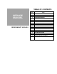
TABLE OF CONTENTS PART SERVICE MANUAL TITLE 1 THE AC GENERATOR 2 ENGINE MECHANICAL 3 GASOLINE FUEL SYSTEM 4 GASEOUS FUEL SYSTEM 5 ENGINE OIL & COOLING SYSTEM 6 ENGINE ELECTRICAL SYSTEM 7 TROUBLESHOOTING 8 SPECIFICATIONS & CHARTS SERIES IMPACT 36 PLUS II
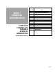
PART 1 GENERAL INFORMATION COMPUTER CONTROLLED VARIABLE SPEED RV GENERATORS SECTION TITLE 1.1 GENERATOR FUNDAMENTALS 1.2 GENERATOR MAJOR COMPONENTS 1.3 OPERATIONAL ANALYSIS 1.4 INSULATION RESISTANCE 1.5 COMPONENTS TESTING 1.6 CONTROL PANEL 1.
NOTES
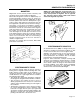
Section 1.1 GENERATOR FUNDAMENTALS MAGNETISM Magnetism can be used to produce electricity and electricity can be used to produce magnetism. Much about magnetism cannot be explained by our present knowledge. However, there are certain patterns of behavior that are known. Application of these behavior patterns has led to the development of generators, motors and numerous other devices that utilize magnetism to produce and use electrical energy. See Figure 1.
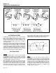
Section 1.1 GENERATOR FUNDAMENTALS Figure 4. Operation of a Simple Generator ALTERNATING CURRENT A simple generator consists of a coil of wires called a Stator and a magnetic field called a Rotor. As the Rotor's magnetic field cuts across the Stator coil, a voltage is induced into the Stator windings. The amount of induced voltage is equal to the strength of the magnetic field. See Figure 4. The current alternates according to the position of the Rotor's poles in relation to the position of the Stator.
Section 1.1 GENERATOR FUNDAMENTALS If OHMS is unknown but VOLTS and AMPERES are known, use the following: VOLTS OHMS = AMPERES REACTANCE IN AC CIRCUITS Figure 6. Electrical Units OHM: The OHM is the unit of RESISTANCE. In every circuit there is a natural resistance or opposition to the flow of electrons. When an EMF is applied to a complete circuit, the electrons are forced to flow in a single direction rather than their free or orbiting pattern.
Section 1.1 GENERATOR FUNDAMENTALS CAPACITIVE REACTANCE: This condition occurs when current leads voltage (Figure 9). It might be thought of as the ability to oppose change in voltage. Capacitance exists in a circuit when certain devices are ~a) capable of storing electrical charges as voltage increases and (b) discharging these stored charges when the voltage decreases. Figure 9.
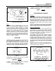
Section 1.1 GENERATOR FUNDAMENTALS 3. When the generator circuit breaker is turned to the “ON” position, AC voltage is delivered to the Full Bridge Rectifier. The AC voltage is rectified to DC and thus becomes DC Link voltage. 4. AC voltage from the stator PS1/PS2 is delivered to the inverter. This is used as the power supply for the inverter circuit board. 5. AC voltage from the stator TIM1/TIM2 is delivered to the system controller. This is used for engine speed sensing. 6.
Section 1.1 GENERATOR FUNDAMENTALS Page 1.
Section 1.2 MAJOR GENERATOR COMPONENTS INTRODUCTION UPPER FAN HOUSING Major components of the generator proper are shown in Figure 1, below. External sheet metal and other unrelated components are omitted from the drawing for clarity. These parts are: As its name implies, this component houses and shields the upper cooling fan. See Figure 1, Item 1.
Section 1.2 MAJOR GENERATOR COMPONENTS ROTOR HUB STEPPER MOTOR See Figure 2 on previous page. The Rotor Hub is balanced with the Rotor and must be replaced with the Rotor as an assembly. Part of the engine ignition system is pressed onto the Hub and can be replaced only as part of the Rotor and Hub assembly. The Stepper Motor (Figure 3) consists of a stepper motor along with a gear and cam arrangement which allows motor movement to change the engine carburetor throttle setting.
Section 1.2 MAJOR GENERATOR COMPONENTS Figure 5. Schematic- Stator Windings Page 1.
Section 1.2 MAJOR GENERATOR COMPONENTS Page 1.
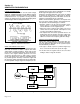
Section 1.3 OPERATIONAL ANALYSIS GENERAL Figure 1, below, is a block diagram of the Impact Plus computer controlled RV generator. The diagram is Intended only for the purpose of illustrating generator operation. Refer to the actual wiring diagram for wiring interconnections. OPERATIONAL DESCRIPTION 1. The Impact Plus is a computer controlled generator that uses an inverter to create a superior sine wave and maintain a steady frequency of 60 Hz.
Section 1.3 OPERATIONAL ANALYSIS OPERATIONAL DESCRIPTION (CONTINUED) 7. The A6060 circuit board controls all functions of the generator, i.e.: a. Engine DC control system b. Stepper motor operation (1) If voltage is low, the board will signal a STEPPER MOTOR to change engine throttle setting and increase speed until the desired voltage level is reached. (2) If voltage goes high, the board will signal the STEPPER MOTOR to reduce engine throttle setting until the desired voltage level is obtained. c.
Section 1.4 INSULATION RESISTANCE DIRT AND MOISTURE If moisture is permitted to remain in contact with the generator Stator windings, some of it will be retained in voids and cracks of the winding insulation. This can eventually cause a reduction in insulation resistance and generator output may be affected. Winding insulation in Generac generators is moisture resistant. However, prolonged exposure to water, high humidity, salt air, etc., will gradually reduce the resistance of winding insulation.
Section 1.4 INSULATION RESISTANCE TEST ALL STATOR WINDINGS TO GROUND Connect the ends of all Stator leads together. Make sure none of the leads are touching any terminal or any part of the generator. Connect one Tester probe to the junction of all Stator leads; the other Tester probe to a clean frame ground on the Stator. Apply a voltage of 1000 volts for about 1 second. Follow the tester manufacturer's instructions carefully.
Section 1.4 INSULATION RESISTANCE ! ! DANGER! DO NOT WORK WITH SOLVENTS IN ANY ENCLOSED AREA. ALWAYS PROVIDE ADEQUATE VENTILATION. FIRE, EXPLOSION OR OTHER HEALTH HAZARDS MAY EXIST UNLESS ADEQUATE VENTILATION IS PROVIDED. WEAR EYE PROTECTION. WEAR RUBBER GLOVES TO PROTECT THE HANDS. CAUTION! Some generators use epoxy or polyester base winding varnishes. Use solvents that do not at tack such materials.
Section 1.4 INSULATION RESISTANCE Page 1.
Section 1.5 COMPONENTS TESTING INTRODUCTION Problems that occur In the computer-controlled RV generator generally involve the following systems or components: 1. The engine. 2. The Speed Control System. 3. The AC Generator. 4. Battery Charge Circuit. 5. A6060 Circuit Board. 6. Wiring Harness and Front Panel. This Section will discuss test procedures for the following components. Also see Part 8 of this Manual, "TROUBLESHOOTING". 1. The AC Generator (Stator). 1. Disconnect the following wires: a.
Section 1.5 COMPONENTS TESTING STATOR ASSEMBLY (CONTINUED) TESTING THE TIMING WINDING: A. To test the Stator Timing winding for an open circuit condition, proceed as follows: 1. Disconnect the 2-pin connector from "J5" of the A6060 circuit board. See Figure 3. a. Stator lead TIM1 (Orange) connects to Pin 1 of the “J5” connector. b. Stator lead TIM2 (Gray) connects to Pin 2 of the “J5” connector. 2. Set a VOM to its "Rx1" scale and zero the meter. 3.
Section 1.5 COMPONENTS TESTING 7. Connect one test lead to Stator lead PS1, the other to Stator lead 77. The VOM should read "infinity". 8. Connect one VOM test lead to Stator lead TIM1, the other test lead to Stator lead 77. "Infinity" should be Indicated. TESTING THE BATTERY CHARGE CIRCUIT GENERAL: The Stator is equipped with dual battery charge windings. These windings deliver an AC output to a Battery Charge Rectifier (BCR) which rectifies it (changes it to direct current or DC).
Section 1.5 COMPONENTS TESTING Page 1.
Section 1.6 CONTROL PANEL CONSTRUCTION COMPONENTS The panel is constructed of sheet metal and includes a panel box, a panel back cover and a front control panel. The panel box is retained to an engine-generator divider plate by five M5 screws. Removal of these screws will permit the panel to be removed from the divider plate and set out of the way with connecting wires still attached. This will allow access to components housed in the control panel.
Section 1.6 CONTROL PANEL Page 1.
Section 1.7 SHEET METAL GENERAL See "Exploded View of Sheet Metal" on next page. A DIVIDER PLATE (Item 1) separates the AC generator components from the engine. The engine Itself is enclosed by a BASE HOUSING WRAPPER (Item 4), a FRAME (Item 24), and a BELLY PAN (Item 23). These components are sealed by means of rubber SEALS (Items 3), to prevent The LOWER FAN attaches to the engine shaft and is enclosed in a LOWER FAN HOUSING (Item 19).
Section 1.7 SHEET METAL EXPLODED VIEW OF SHEET METAL (GASOLINE UNITS) 1 2 59 30 39 44 22 4 38 3 5 3 57 4 78 3 59 9 69 57 5 20 21 24 69 22 59 25 39 3 65 29 3 69 34 59 45 44 30 53 33 67 64 68 32 7 53 35 30 29 7 6 8 23 5 62 31 5 61 50 5 63 64 40 41 TO CARBURETOR 26 81 37 47 71 7 5 60 37 28 27 75 30 48 5 13 42 19 77 78 79 73 12 49 39 72 54 74 59 18 70 80 5 17 Page 1.
Section 1.7 SHEET METAL PARTS LIST FOR SHEET METAL (GASOLINE UNITS) ITEM 1 2 3 4 5 6 7 8 9 12 13 17 18 19 20 21 22 23 24 25 26 27 28 29 30 31 32 33 34 35 36 37 38 39 40 41 QTY 1 2 1 1 31 2 12 4 2 1 1 1 1 1 1 1 1 1 1 1 1 1 1 3 7 1 1 1 1 4 1 5 1 4 2 2 DESCRIPTION PLATE, DIVIDER M6-1.0 HEX NUT SEAL RUBBER EXTRUSION 3.5 FT WRAPPER, BOX TAPTITE, M5- .8 x 10MM LONG MOUNTING RAILS M8 LOCK WASHER M8-1.25 x 35MM HEX HD. CAPSCR. HHCS M5-0.
Section 1.7 SHEET METAL EXPLODED VIEW OF SHEET METAL (LP UNITS) 1 75 30 44 22 4 38 3 11 3 4 3 2 11 5 20 21 24 43 22 2 25 39 3 37 33 30 53 29 27 2 45 44 65 3 43 34 47 30 59 67 64 68 36 7 81 51 35 58 49 57 51 9 7 6 8 23 62 43 5 50 60 61 55 63 64 51 78 32 53 7 30 29 40 41 48 5 51 42 5 19 5 12 71 2 18 80 5 17 75 26 30 77 78 79 73 39 72 54 74 70 76 Page 1.
Section 1.7 SHEET METAL PARTS LIST FOR SHEET METAL (GASOLINE UNITS) ITEM 1 2 3 4 5 6 7 8 9 11 12 17 18 19 20 21 22 23 24 25 26 27 29 30 31 32 33 34 35 36 37 38 39 40 41 42 QTY 1 32 3.5' 1 31 2 12 4 3 1 1 1 1 1 1 1 1 1 1 1 1 1 5 9 1 1 1 1 4 1 1 1 2 2 2 2 43 7 DESCRIPTION PLATE, DIVIDER CRIMPTITE 10-24 x 1/2" SEAL, RUBBER EXTRUSION BOX, WRAPPER TAPTITE, M5-.8 x 10MM MOUNTING RAILS M8 LOCK WASHER M8-1.25 x 35MM HEX HD. CAPSCR. HHCS M5-0.
Section 1.7 SHEET METAL Page 1.
PART 2 ENGINE MECHANICAL COMPUTER CONTROLLED VARIABLE SPEED RV GENERATORS Series Impact 36 Plus SECTION TITLE 2.1 GENERAL INFORMATION 2.2 VALVE TRAIN 2.3 PISTON, RINGS, CONNECTING ROD 2.
NOTES
Section 2.1 GENERAL INFORMATION INTRODUCTION The engine used on Impact 36 plus Series recreational vehicle AC generators is a Generac Series GV-220, vertical shaft, single cylinder, overhead valve type. These engines are not equipped with a mechanical engine governor. Instead. variable engine speeds are controlled by a computer circuit board. The circuit board signals a stepper motor to move the carburetor throttle linkage. 4-CYCLE ENGINE THEORY Figure 1.
Section 2.1 GENERAL INFORMATION TIMING: Valve timing and ignition timing must be precisely controlled if the engine is to operate properly and efficiently. Intake and exhaust valves must open and close in a precise timed sequence if the four strokes are to occur. Ignition must occur at exactly the correct piston position, just prior to the start of the power stroke.
Section 2.1 GENERAL INFORMATION Engine crankcase oil capacity without oil filter change is about 29 fluid ounces (850m. Engine crankcase oil capacity (with oil filter change) is about 1 U.S. quart (946m1). Change engine oil and the oil filter after the first eight (8) hours of operation. Thereafter, change engine oil and oil filter every 50 operating hours. NOTE: Additional Information on the engine oil system can be found in Part 5 of this manual, "Engine Oil and Cooling System". STORAGE INSTRUCTIONS 2.
Section 2.
Section 2.2 VALVE TRAIN VALVE TRAIN COMPONENTS Valve train components are listed below and shown in Figure 1, below. ITEM 1 2 3 4 5 6 7 8 9 10 11 QTY 2 2 2 2 2 1 2 2 2 1 1 DESCRIPTION Tappet Push Rod Rocker Arm Pivot Ball Stud Rocker Arm Jam Nut Push Rod Guide Plate Valve Spring Valve Spring Retainer Valve Spring Washer Exhaust Valve Intake Valve Figure 2. Removal of Rocker Arm over 2. Loosen the rocker arm jam nuts on the pivot ball studs. Then, loosen the pivot ball studs.
Section 2.2 VALVE TRAIN VALVES: Replace valves If they are damaged, distorted or if the margin is ground to less than 0.039 inch (1.0mm). If the valves are in useable condition, use a valve grinder to grind the faces to a 45' angle. Check valve stem diameter. After the valves have been reconditioned, they should be lapped with a suitable lapping tool and valve lapping compound. VALVE SERVICE Figure 4. Cylinder Head Removal ! DANGER! ALWAYS WEAR SAFETY GLASSES WHEN REMOVING THE VALVE SPRINGS. 5.
Section 2.2 VALVE TRAIN NOTE: After the valve guides have been oversized, be sure to recut the valve seats so they will align with the guides. Figure 10. Valve Spring Figure 8. Valve Guides VALVE TAPPETS: Valve tappets can be removed during removal of the engine camshaft. Intake and exhaust valve tappets are identical. However, once a wear pattern has been established the two tappets should not be Interchanged. VALVE SPRING FREE LENGTH GV-220: 2.0741inch (52.69mm) FORCE REQUIRED TO COMPRESS SPRING TO 1.
Section 2.2 VALVE TRAIN VALVE COMPONENTS INSTALLATION (CONTINUED) 3. Install the valve spring washers, valve springs and valve spring retainers over the valve guides. a. Hold the valve with your fingers and use your thumbs to compress the spring. b. When the spring is compressed sufficiently, slide the spring retainer small opening over the valve stem. c. With the smaller retainer opening around the valve stem, release the spring. 6. Place the push rod guide plate into position on the head.
Section 2.2 VALVE TRAIN VALVE CLEARANCE GV-220 ENGINE INTAKE VALVE: 0.001-0.0022 inch (0.03-0.056mm) EXHAUST VALVE: 0.0018-0.003 inch (0.046-0.07mm) Adjust the valve clearance as follows: 1. Rotate the crankshaft until the piston is at top dead center (TDC) of its compression stroke. Both valves should be closed. 2. Loosen the rocker arm jam nut. 3. Use an alien wrench to turn the pivot ball stud while checking the clearance between the rocker arm and the valve stem with a feeler gauge. Figure 17.
Section 2.2 VALVE TRAIN Page 2.
Section 2.3 PISTON, RINGS, CONNECTING ROD OVERSIZE PISTON & RINGS Worn or scored cylinders may be rebored to 0.010 (0.25mm) or 0.020 (0.50mm) oversize. Pistons and piston rings of matching oversize are available to fit the rebored cylinder. F figure 2. Piston Pin Removal Figure 1. Piston, Rings and Connecting Rod CHECK FOR PISTON WEAR: The piston is slightly elliptical. It's smaller diameter is in line with the wrist pin boss. It's larger diameter is 90° from the wrist pin boss.
Section 2.3 PISTON, RINGS, CONNECTING ROD 5. Ring to Groove Side Clearance:- Clean carbon from piston ring grooves as. Install new rings. Use a feeler gauge to measure the side clearance between the rings and ring grooves. If ring-togroove side clearance exceeds the stated limits, replace the piston. RING TO GROOVE SIDE CLEARANCE (GV-220) 0.0004-0.0014 inch (0.012-0.034mm) Figure 4. Piston Minor Diameter PISTON MINOR DIAMETER GV-220) Design DIAMETER: 2.747-2.748 inch (69.789-69.809mm) Figure 5.
Section 2.3 PISTON, RINGS, CONNECTING ROD CONNECTING ROD The connecting rod is manufactured of die cast aluminum. Alignment marks are provided on the rod and on the connecting rod cap. Be sure to align these marks when assembling the rod to the crankshaft. Connecting rod bolts are of the "washerless" type. The connecting rod and the connecting rod cap are a matched set and must be replaced as a matched set. Figure 7.
Section 2.3 PISTON, RINGS, CONNECTING ROD hammer handle to gently tap the piston down into the cylinder. 4. Check that the connecting rod's large diameter bearing is coated with oil, as well as the crank throw and the connecting rod cap. 5. Guide the large end of the connecting rod onto the crankshaft. Install the connecting rod cap. The match mark on the cap must be aligned with an identical mark on the rod (Figure 10). 6. Install the connecting rod cap bolts and tighten to the proper torque.
Section 2.4 CRANKSHAFT AND CAMSHAFT GENERAL CRANKSHAFT REMOVAL Prior to removal of the crankcase cover, gain access to the engine and generator by removing surrounding sheet metal as required. See Section 1.6. See Figure 3. To remove the crankshaft, proceed as follows: 1. The engine flywheel must be removed before the crankshaft can be removed. CRANKCASE COVER REMOVAL Before attempting to remove the crankcase cover, remove rust, paint and burrs from the power takeoff (PTO) end of the crankshaft.
Section 2.4 CRANKSHAFT AND CAMSHAFT CAMSHAFT INSPECTION Carefully inspect the entire camshaft for wear, nicks, damage. All areas indicated in Figure 4 should be checked for wear. • Inspect the crankpin for damage, nicks, scratches, etc. Small nicks and scratches may be polished out using fine emery cloth. ALL EMERY RESIDUE MUST BE REMOVED. Use a solvent (such as kerosene) to remove emery residue. • Carefully measure the outside diameter (O.D.
Section 2.4 CRANKSHAFT AND CAMSHAFT Figure 6. Bearing Bore in Crankcase Cover Figure 8. Measuring Compression Release Lift COMPRESSION RELEASE MECHANISM INSTALLING THE CRANKSHAFT A mechanical compression release is provided on the camshaft. See Figure 7. A PIN extends over the cam lobe. This PIN pushes on the tappet, to lift the valve and relieve compression for easier cranking. When the engine starts, centrifugal force moves the FLYWEIGHT outward against SPRING force.
Section 2.4 CRANKSHAFT AND CAMSHAFT Figure 9. Timing Mark on Crankshaft Gear Page 2.3-8 Figure 10.
PART 3 GASOLINE FUEL SYSTEM COMPUTER CONTROLLED VARIABLE SPEED RV GENERATORS Series Impact 36 Plus SECTION TITLE 3.1 INTRODUCTION TO FUEL SYSTEM 3.2 AIR CLEANER & AIR INTAKE 3.3 FILTER & FUEL PUMP 3.4 CARBURETOR 3.5 AUTOMATIC CHOKE 3.
NOTES Page 2
Section 3.1 INTRODUCTION TO FUEL SYSTEM GENERAL Recreational vehicle generators equipped with a gasoline fuel system are usually installed so that they share the fuel supply tank with the vehicle engine. When this is done, the generator Installer must never tee off the vehicle fuel supply line to deliver fuel to the generator. When the generator fuel supply line is teed off the vehicle's fuel supply line, the more powerful vehicle engine's fuel pump will starve the generator when both are running.
Section 3.1 INTRODUCTION TO FUEL SYSTEM altered. Service technicians working on the RV generator systems must not do anything that might change the vehicle fuel system design. Figure 2. Typical Gasoline Fuel System Page 3.
Section 3.2 AIR CLEANER AND INTAKE AIR CLEANER 4. Clean the air cleaner BASE and COVER, then install the new PAPER FILTER Into COVER. DESCRIPTION: The air cleaner assembly consists of (a) an air cleaner BASE, (b) a PAPER FILTER, and (c) a COVER. See Figure 1. 5. Install COVER with PAPER FILTER. Retain to BASE with two screws. AIR INTAKE See Figure 2. Air is drawn into the air cleaner, passes through the air cleaner filter, and is then ported to the carburetor air inlet through an air intake hose.
Section 3.2 AIR CLEANER AND INTAKE Page 3.
Section 3.3 FUEL FILTER AND FUEL PUMP FUEL FILTER The fuel filter should be removed and replaced every 100 hours of operation or once each year, whichever occurs first. TESTING THE PUMP: 1. The pump coil can be tested for an open or shorted condition as follows: a. Test for "Open": (1) Disconnect the RED pump wire at its "bullet" lug. (2) Set a VOM to its "Rx1 " scale and zero the meter. (3) Connect one meter test probe to the RED pump wire, the other test probe to terminal end of the pump's BLACK lead.
Section 3.3 FUEL FILTER AND FUEL PUMP Page 3.
Section 3.4 CARBURETOR GENERAL INFORMATION Proper engine performance depends on the carburetion system. The use of clean, fresh gasoline and a well-maintained air cleaner are extremely important to proper operation, as well as engine reliability and power. Most causes of carburetion problems are related to the use of stale, gummy fuel and the ingestion of dirt. Before servicing the carburetor, be sure to check for evidence of these conditions.
Section 3.4 CARBURETOR CARBURETOR DISASSEMBLY See Figure 3. The carburetor can be disassembled as follows: 1. Remove the BOWL NUT (Item 3) and the FIBER WASHER (Item 4). Then, remove the FLOAT BOWL (Item 5). 2. Remove the FLOAT PIN (Item 6). Then, remove the FLOAT (Item 7) and the INLET VALVE (Item 8). 3. Remove the IDLE SPEED SCREW (Item 20) with SPRING (Item 19). 4. Rotate the THROTTLE VALVE (Item 10) to its closed position and remove the SCREW (Item 9). Remove the THROTTLE VALVE. 5.
Section 3.4 CARBURETOR ADJUSTMENT The carburetor used on the GV-220 engine has a FIXED, NON-ADJUSTABLE Low Speed Jet. ENGINE SPEED Engine speed is controlled by the A6060 circuit board. That circuit board signals a stepper motor which moves the throttle linkage. Engine speed will vary in response to changes in generator AC output voltage. The circuit board monitors the demand for power and adjusts the engine speed accordingly. This permits the engine to deliver only the power needed.
Section 3.4 CARBURETOR Figure 6. Carburetor Removal Page 3.
Section 3.5 AUTOMATIC CHOKE GENERAL The GV-220 vertical shaft engines are equipped with an automatic choke. A choke solenoid is attached to the carburetor choke shaft by means of a choke control link. Solenoid operation is controlled by the A6060 circuit board. The circuit board energizes and deenergizes the solenoid cyclically at a rate dependent on ambient temperature during engine cranking only. DESCRIPTION See Figure 1. The CHOKE SOLENOID is retained to a CHOKE COVER by two No.
Section 3.5 AUTOMATIC CHOKE Page 3.
Section 3.6 SPEED CONTROL SYSTEM GENERAL The AC generator's output voltage is controlled by a "computerized" speed control system. This system changes engine speed in response to changes in the AC output voltage at varying engine loads. The speed control system consists of (a) the A6060 circuit board and (b) a stepper motor. A6060 CIRCUIT BOARD This circuit board utilizes a closed-loop, proportionalderivative controller circuit which regulates the generator's RMS voltage by changing engine speed.
Section 3.6 SPEED CONTROL SYSTEM ELECTRICAL CONNECTIONS BROKEN: If one or more of the electrical connections to the stepper motor are broken or disconnected, either of the following might occur: 1. The stepper motor may not turn at all. 2. The stepper motor may turn erratically. If the stepper motor does not turn, symptoms will be the same as for a failed or seized stepper motor. LEADS CONNECTED WRONG: Incorrectly connected electrical leads to the stepper motor can result in any one of the following: 1.
PART 4 GASEOUS FUEL SYSTEM COMPUTER CONTROLLED VARIABLE SPEED RV GENERATORS Series Impact 36 Plus SECTION TITLE 4.1 INTRODUCTION TO FUEL SYSTEM 4.2 SHUTOFF VALVE & REGULATOR 4.3 CARBURETOR NOTE: Information on the following is the same as for the "GASOLINE FUEL SYSTEM" (Part 3): Air Cleaner & Air Intake (Section 3.2) Speed Control System (Section 3.
NOTES
Section 4.1 INTRODUCTION TO FUEL SYSTEM GENERAL INFORMATION Some RV generator models are equipped with fuel systems that utilize LP gas as a fuel. The initials "LP" stand for "liquefied petroleum". This gas is highly volatile and can be dangerous if handled or stored carelessly. All applicable laws, codes and regulations pertaining to the storage and handling of LP gas must be complied with. The installation of such fuel systems must also be in compliance with such laws, codes and regulations.
Section 4.1 INTRODUCTION TO FUEL SYSTEM IMPORTANT CONSIDERATIONS (CONTINUED) NOTE: A PRIMARY REGULATOR, between the tank and the fuel lockoff solenoid, is required to ensure that correct gas pressure is delivered to the lockoff solenoid. • The generator installer's connection point is at the fuel lockoff solenoid which has a 3/4 inch (female) connection. • A length of flexible hose is required between the fuel lockoff solenoid and rigid fuel piping, to allow for vibration and/or shifting of the unit.
Section 4.1 INTRODUCTION TO FUEL SYSTEM GASEOUS CARBURETION LEAKAGE TESTING Gas at positive pressure is delivered from the fuel lockoff solenoid to the inlet of the regulator (about 1114 inches of water). As the engine piston moves downward on its intake stroke, air is drawn into the area above the piston through the carburetor venturi. A negative pressure is created at the venturi which is proportional to the amount of air that is flowing.
Section 4.1 INTRODUCTION TO FUEL SYSTEM Page 4.
Section 4.2 SHUTOFF VALVE AND REGULATOR GENERAL ADJUSTMENTS See Figure 1. The fuel shutoff valve (lockoff solenoid) and the secondary regulator are retained to a flat mounting bracket which, in turn, mounts to the generator base cover. The fuel lockoff solenoid is retained to the mounting bracket by means of a u-bolt. The secondary regulator is retained to the mounting bracket with two 1/4"-20 x 3/4" long capscrews. ITEM QTY DESCRIPTION 1 1 LP Gas Regulator 2 1 Fuel Lockoff Solenoid 3 1 U-Bolt-1.
Section 4.2 SHUTOFF VALVE AND REGULATOR TEST PROCEDURE: 1. Set a volt-ohm-milliammeter (VOM) to read battery voltage (12 VDC). 2. Connect the VOM test leads across Wire 14 (Red) at the solenoid and a clean frame ground. 3. Set the fuel primer switch on the generator panel to its ON position. a. The meter should indicate battery voltage. b. The solenoid should energize open. RESULTS OF TEST: 1. If battery voltage is Indicated but the solenoid does NOT energize, replace the lockoff solenoid. 2.
Section 4.3 CARBURETOR GENERAL DISASSEMBLY AND REASSEMBLY The carburetor is designed for use with LP gas in its vapor form. The following specifications apply: The carburetor is replaced as an entire assembly. Disassembly and reassembly is not required. Carburetor Inlet Diameter...........1.02inch (26mm) Carburetor Outlet Diameter ........0.78 inch (20mm) Venturi Diameter ........................0.63 inch (16mm) Main Jet Diameter Number ..................................370 Measured Size ..............
Section 4.3 CARBURETOR Page 4.
PART 5 ENGINE OIL & COOLING SYSTEM COMPUTER CONTROLLED VARIABLE SPEED RV GENERATORS Series Impact 36 Plus SECTION TITLE 5.1 ENGINE OIL SYSTEM 5.
NOTES
Section 5.1 ENGINE OIL SYSTEM INTRODUCTION TO OIL SYSTEM The engine oil system serves to (a) reduce friction between parts, (b) cool the engine, and (c) establish a slightly negative pressure in the crankcase to prevent oil leakage. Major components that will be discussed in this section include the following: • Oil Pickup Screen. • Oil Pump. • Crankshaft Oil Seals. • Pressure Relief Valve. • Breather Assembly. • Oil Sump. • Oil Filter Support Assembly.
Section 5.1 ENGINE OIL SYSTEM OIL PUMP (CONTINUED) PRESSURE RELIEF VALVE INSPECTION (CONT'D): Inspect the outer drive pins on the camshaft. Look for breakage, bending, other damage. These are roll pins which can be removed and replaced. DESCRIPTION: A ball type pressure relief valve is located in a bore of the crankcase. The ball and spring are retained in the crankcase bore by a spring retainer. The Relief Valve serves to limit oil pressure to a maximum value.
Section 5.1 ENGINE OIL SYSTEM The breather serves to maintain a partial vacuum in the engine crankcase, to prevent oil from being forced past oil seals, gaskets or rings. See Figure 6. A reed type breather valve permits excess pressure to be vented out of the crankcase and to atmosphere through a breather tube. A breather retainer limits the movement of the breather valve. Two small oil return holes in the breather cup allow condensed oil vapors to drain back to the crankcase.
Section 5.1 ENGINE OIL SYSTEM Page 5.
Section 5.2 ENGINE COOLING SYSTEM It is absolutely essential that an adequate flow of air for cooling, ventilating and engine combustion be supplied to the generator set. Without sufficient air flow, the engine-generator quickly overheats. Such overheating can cause serious operating difficulties and may also cause fire and personal injury. The installer must make sure that sufficient air is available to the generator for cooling, ventilating and combustion.
Section 5.2 ENGINE COOLING SYSTEM COMPENSATING FOR RESTRICTIONS Figure 3 — Suspended Mount Inlet Door Such materials as screening, louvers, or expanded metal can restrict the free flow of air. Compensate for this restriction by making the actual air opening proportionately larger. Some materials may offer only a 60 percent “free air inlet area.” Other more efficient materials may provide up to a 90 percent free air inlet area.
PART 6 ENGINE ELECTRICAL SYSTEM COMPUTER CONTROLLED VARIABLE SPEED RV GENERATORS Series Impact 36 Plus SECTION TITLE 6.1 ENGINE DC CONTROL SYSTEM 6.2 A6060 CIRCUIT BOARD 6.3 ENGINE CRANKING SYSTEM 6.4 ENGINE IGNITION SYSTEM 6.5 ENGINE SHUTDOWN FEATURES 6.
NOTES
Section 6.1 ENGINE DC CONTROL SYSTEM GENERAL The engine DC control system consists of all those electrical components required for cranking, starting and running the engine. These components include the following: 1. Engine cranking system components a. A 12 VDC battery. b. A Start-Run-Stop Switch (SW1). c. A Starter Contactor (Starter Relay)-(SC). d. A Starter Motor (SM). 3. Engine Ignition System Components. a. Ignition Module (IM). b. Ignition Sensor (IS). c. Ignition Coil (IC). d. Spark Plug (SP). 4.
Section 6.1 ENGINE DC CONTROL SYSTEM HOW IT WORKS ENGINE NOT RUNNING: 1. Battery output (12VDC) is available to the contacts of a starter contactor (SC). However, the contacts are open. 2. Battery output is delivered to Terminals J2 - 5 of the A6060 circuit board, via Wire 13, a 15 amp fuse, and Wire 15. Circuit board action holds this circuit open. 3. Battery output is available to a Battery Charge Rectifier (BCR) via Wire 13, 15 amp Fuse (F1), Wire 15, a Resistor (R1) and Wire 15A.
Section 6.2 A6060 CIRCUIT BOARD GENERAL The A6060 circuit board controls all phases of engine operation including cranking, starting, running and shutdown. The circuit board interconnects with other components of the engine electrical system. The board Is powered by fused 12 VDC battery output, available to the board via Wire 15. Figure 2.
Section 6.2 A6060 CIRCUIT BOARD CIRCUIT BOARD CONNECTIONS (CONTINUED) RECEPTACLE J4: The A6060 circuit board mounts a 3-pin receptacle J4. A 3-pin connector plug connects to the A6060. This harness then connects to Bridge Rectifier. DC Link Voltage is supplied to the circuit board for voltage sensing. RECEPTACLE J5: The A6060 circuit board mounts a 2-pin receptacle J5. A 2-pin connector plug connects to the A6060. This harness then connects to TIM1/TIM2.
Section 6.3 ENGINE CRANKING SYSTEM INTRODUCTION BATTERY COMPONENTS: The engine cranking system is shown schematically in Figure 1, below. The system consists of the following components: • A 12 volts Battery. • A Start-Run-Stop Switch (SW1). • A Starter Contactor (SC). • A Starter Motor (SM1). • A6060 Circuit Board. • Interconnecting wires. RECOMMENDED BATTERY: The battery is generally supplied by the customer.
Section 6.3 ENGINE CRANKING SYSTEM BATTERY (CONTINUED) TESTING A BATTERY: The best method of testing a battery is with an automotive type battery hydrometer. Some "Maintenance Free" batteries cannot be tested with a hydrometer. Most batteries can be tested for both STATE OF CHARGE and CONDITION as follows: 1. Test for State of Charge: a. Follow the hydrometer manufacturer's instructions carefully. Test the specific gravity of the fluid in all battery cells. b.
Section 6.3 ENGINE CRANKING SYSTEM STARTER MOTOR DESCRIPTION: The Starter Motor is a 12 volts negative ground type. It is capable of operating on heavy duty battery input at temperatures as low as -30 F. without any significant change in performance. Its pinion is a 10-tooth type having a 20- pressure angle. Figure 3. Starter Contactor TESTING: Connect the test leads of a VOM across the Starter Motor terminal and case. Hold the Start-Run-Stop switch at "START".
Section 6.3 ENGINE CRANKING SYSTEM Page 6.
Section 6.4 ENGINE IGNITION SYSTEM INTRODUCTION The engine ignition system consists of the following major components: • Ignition Cage Assembly. • Ignition Sensor Assembly. • Ignition Module (IM). • Ignition Coil (IC). • Spark Plug (SP1). As the generator's Permanent Magnet Rotor turns during operation, magnets on the Ignition Cage rotate past the Ignition Sensor to induce a timed low voltage pulse into the Sensor.
Section 6.4 ENGINE IGNITION SYSTEM IGNITION MODULE (CONTINUED) Clean the Spark Plug and reset its gap to 0.030 inch (0.76mm) every 100 hours of operation. Clean by scraping or wire brushing and washing with commercial solvent. DO NOT blast clean the spark plug. SUMMARY OF OPERATION Figure 4. Ignition Module IGNITION COIL Primary ignition voltage (12 VDC) is delivered from the Ignition Module to the Ignition Coil. The Coil boosts the voltage and delivers the high voltage to the engine Spark Plug.
Section 6.4 ENGINE IGNITION SYSTEM TESTING FOR SPARK: To test the ignition system, a suitable spark tester may be used. Such spark testers are commercially available. Test the system as follows: ! Warning! Do NOT use a screwdriver to test for spark. Personal injury or damage to equipment may result. 1. Disconnect the high tension lead from the spark plug. 2. Attach the spark plug high tension lead to the spark tester terminal.
Section 6.4 ENGINE IGNITION SYSTEM TESTING THE SYSTEM (CONTINUED) CHECK POWER SUPPLY (CONT’D): b. If battery voltage is NOT indicated in Step 7, test Wire 14 between the 4-terminal connector and the A6060 circuit board. Repair or replace as necessary. CHECK IGNITION SENSOR: 1. In the 3-pin connector plug half from the Ignition Module, locate FEMALE Pin 1 to which the BROWN wire connects. 2. Connect a jumper wire from FEMALE Pin 1 (BROWN wire) to frame ground. 3.
Section 6.5 SHUTDOWN FEATURES GENERAL The engine mounts an Oil Pressure Switch (LOP) and an Oil Temperature Switch (HTO). These two switches, in conjunction with the A6060 circuit board, protect the engine against (a) low oil pressure and (b) high oil temperature. The engine protective circuit Is shown in Figure 1. OIL PRESSURE SWITCH DESCRIPTION: The Oil Pressure Switch has normally-closed contacts which are held open by engine oil pressure during cranking and running.
Section 6.5 SHUTDOWN FEATURES ADDITIONAL SHUTDOWN FEATURES The A6060 Circuit Board also incorporates the following protective shutdown features: LOSS OF 12-PIN CABLE SIGNALS TO INVERTER: The generator will shutdown if the 12-pin connector is disconnected from the inverter when CB1 is turned to ON. This shutdown will occur after approximately 5-7 seconds. LOSS OF TIM1/TIM2 INPUT TO A6060 CIRCUIT BOARD: If Timing Winding input is lost, the generator will immediately shutdown.
Section 6.6 OPTIONAL REMOTE PANEL GENERAL An optional remote-mounted Start-Stop panel is available. This panel will permit the generator to be started and stopped from some convenient remote location in the recreational vehicle. REMOTE PLUG-IN RECEPTACLE A plug-in receptacle (Figure 2.24) is provided on the generator set, near the DC power wires. Use this receptacle to connect an optional remote-mounted start/stop panel to the generator.
Section 6.6 OPTIONAL REMOTE PANEL Page 6.
PART 7 TROUBLESHOOTING SECTION TITLE 7.1 GENERATOR & SPEED CONTROL 7.
NOTES
Section 7.1 GENERATOR & SPEED CONTROL SYSTEM TROUBLESHOOTING REFERENCE CHART PROBLEM POSSIBLE CAUSE REMEDY PAGE 1. Engine starts, accelerates, shuts down at 4500 rpm a. Carburetor linkage sticking with throttle stuck open. b. Stepper Motor failed or seized. c. Stepper Motor wire connections broken or disconnected. d. Stepper Motor not properly connected. a. Repair sticking throttle 3.4-3 b. Replace Stepper Motor. c. Reconnect or repair. 3.6-1 3.6-1 d. Reconnect wires. 3.6-1 a.
Section 7.1 GENERATOR & SPEED CONTROL SYSTEM Page 7.
Section 7.2 ENGINE DC CONTROL SYSTEM / AC TROUBLESHOOTING INTRODUCTION This Section contains troubleshooting information pertaining to the engine DC control system. The section is divided into two parts, i.e., troubleshooting flow charts and diagnostic test procedures. Use the flow charts and the test procedures in conjunction with one another. The first step in troubleshooting is to identify the problem. After identifying the problem, go to the flow chart that best describes it.
Section 7.2 ENGINE DC CONTROL SYSTEM / AC TROUBLESHOOTING PROBLEM 2 - ENGINE WILL NOT CRANK PROBLEM 3 - ENGINE CRANKS BUT WILL NOT START Page 7.
Section 7.2 ENGINE DC CONTROL SYSTEM / AC TROUBLESHOOTING PROBLEM 3 - ENGINE CRANKS BUT WILL NOT START (CONTINUED) Page 7.
Section 7.2 ENGINE DC CONTROL SYSTEM / AC TROUBLESHOOTING PROBLEM 4 - ENGINE STARTS HARD AND RUNS ROUGH Page 7.
Section 7.2 ENGINE DC CONTROL SYSTEM / AC TROUBLESHOOTING PROBLEM 5 - ENGINE STARTS THEN SHUTS DOWN AFTER A FEW SECONDS 12 SHUTS DOWN TEST 31 TEST INVERTER (Pg. 7.2-18) FAIL REPLACE INVERTER Page 7.
Section 7.2 ENGINE DC CONTROL SYSTEM / AC TROUBLESHOOTING PROBLEM 6 - GENERATOR DOESN’T PULL FULL LOAD PROBLEM 7 - GENERATOR CIRCUIT BREAKER TRIPS / NO AC VOLTAGE Page 7.
Section 7.2 ENGINE DC CONTROL SYSTEM / AC TROUBLESHOOTING PROBLEM 8 - ENGINE SHUTS DOWN UNDER LOAD PROBLEM 9 - GENERATOR LOSES AC POWER THEN SHUTS DOWN 12 Page 7.
Section 7.2 ENGINE DC CONTROL SYSTEM / AC TROUBLESHOOTING PROBLEM 10 - NO AC OUTPUT 12-WIRE 12 Page 7.
Section 7.2 ENGINE DC CONTROL SYSTEM / AC TROUBLESHOOTING PROBLEM 10 - NO AC OUTPUT (CONTINUED) Page 7.
Section 7.2 ENGINE DC CONTROL SYSTEM / AC TROUBLESHOOTING TEST 1- CHECK 7.5 AMP FUSE DISCUSSION: The panel-mounted 7.5 amp fuse is connected in series with the 12 VDC power supply to the engine DC control system. A blown fuse will prevent engine priming, cranking and running. TEST PROCEDURE: Push in on fuse holder cap and turn it counterclockwise to remove cap and fuse. Check the fuse visually. If the fuse metal element has melted open, replace the fuse.
Section 7.2 ENGINE DC CONTROL SYSTEM / AC TROUBLESHOOTING RESULTS: 1. If unit is being tested because the priming function doesn't work: a. !f battery voltage is good but the pump doesn't work, go to Test 5. b. !f battery voltage is NOT indicated, go to Test 6. 2. If engine cranks but will not start: a. !f battery voltage is good but the pump doesn't work, go to Test 5. b. If DC power to pump is good and pump works, go to Test 22.
Section 7.2 ENGINE DC CONTROL SYSTEM / AC TROUBLESHOOTING This test will determine if battery voltage is available to the Starter Motor for cranking the engine. TEST PROCEDURE: 1. Set a VOM to read battery voltage (12 VDC). 2. Connect the meter test leads across the starter terminal and frame ground. 3. Set the Start-Run-Stop switch to "START". The meter should indicate battery voltage. RESULTS: 1. No power to Wire 56 terminal, go to Test 10. 2. If power to Starter Contactor is good, go to Test 11. 3.
Section 7.2 ENGINE DC CONTROL SYSTEM / AC TROUBLESHOOTING TEST 11- TEST STARTER CONTACTOR 2. If engine stops when Wire 18 is grounded but will not shut down with Start-Stop switch, replace the Switch. DISCUSSION: See "Starter Contactor" on Page 6.3-2. Replace Starter Contactor if bad. 3. If engine will not crank when Wire 17 is grounded, replace the A6060 circuit board.
Section 7.2 ENGINE DC CONTROL SYSTEM / AC TROUBLESHOOTING 2. Connect the VOM test leads across the 4-tab connector and frame ground. 3. Hold the engine Start-Stop switch at "START". The meter should read battery voltage. RESULTS: 1. If DC voltage is NOT indicated, go to Test 21. 2. If DC voltage is good, go on to Test 18. Figure 8. Checking Spark Plug Gap RESULTS: 1. Clean and regap or replace spark plug as necessary. TEST 18- CHECK IGNITION SENSOR 2.
Section 7.2 ENGINE DC CONTROL SYSTEM / AC TROUBLESHOOTING If the engine cranks but won't start, it is possible that a failure in the circuit board has occurred and DC power is not being delivered to the Wire 14 circuit. This test will determine if circuit board action will deliver battery voltage to the necessary engine components. PROCEDURE: Set a VOM to read battery voltage.
Section 7.2 ENGINE DC CONTROL SYSTEM / AC TROUBLESHOOTING ENGINE COMPRESSION PRESSURE NOMINAL PRESSURE: 60 psi MINIMUM ALLOWABLE: 55 psi NOTE: Full compression pressure cannot be obtained at cranking speeds, due to the action of a compression release mechanism. RESULTS: If compression is poor, look for one or more of the following possible causes: 1. Loose cylinder head bolts. 2. Failed cylinder head gasket. 3. Burned valves or valve seals. 4. Insufficient valve clearance.
Section 7.2 ENGINE DC CONTROL SYSTEM / AC TROUBLESHOOTING TEST 29 - 12 POSITION HARNESS CONTINUITY TEST 1) Set VOM to measure Resistance. 2. Measure from pin location #1 on one end of the 12 position harness to pin location #1 on the opposite end of the harness. A reading of “Continuity” should be measured. Repeat procedure for each pin position on the 12-wire harness. If an open condition is detected, replace the defective harness as necessary. 3.
Section 7.2 ENGINE DC CONTROL SYSTEM / AC TROUBLESHOOTING TEST 31 - STATIC TESTS ON INVERTER ASSUMPTION: • Inverter not connected to generator. • Inverter has been disconnected for at least 5 minutes from running genset to allow capacitors to discharge. STATOR TESTS TEST 32 - POWER SUPPLY WINDING TEST 1. Disconnect the 12 position cable from the inverter. 2. Start the unit with CB1 in the OFF position. TEST PROCEDURE: 1. Set a DVOM to DIODE RANGE.
Section 7.2 ENGINE DC CONTROL SYSTEM / AC TROUBLESHOOTING 5. Momentarily jump Wire #15 (located at the fuse holder) to Wire #56 (located at the Starter Contactor). This will initiate cranking of the engine. The generator will start, but the throttle will need to be controlled manually. Hold the throttle at about a half load setting. 4. Instal paper clips in connector to use as a test point. 6. Set a VOM to measure AC. Measure the AC voltage at the timing winding connector (orange and grey wires).
Section 7.2 ENGINE DC CONTROL SYSTEM / AC TROUBLESHOOTING Page 7.
PAGE PART 8 SPECIFICATIONS AND CHARTS COMPUTER CONTROLLED VARIABLE SPEED RV GENERATORS Series Impact 36 Plus TITLE 8-1 General Specifications 8-1 Nominal Resistances of Generator Windings 8-2 Electrical Schematic 8-3 Wiring Diagram 8-4 to 8-8 Engine Specifications 8-9 Engine Torque Specifications 8-10 Major Features and Dimensions
NOTES
Part 8 SPECIFICATIONS & CHARTS TYPE Impact 36 G Impact 36 LP MODEL 0940 0941 TYPE OF ROTOR Permanent Magnet Type Permanent Magnet Type RATED WATTS 3600 3400 RATED VOLTS 115 115 PHASE 1-Phase 1-Phase RATED MAXIMUM LOAD AMPERES 30.0 28.
Part 8 SPECIFICATIONS & CHARTS ELECTRICAL SCHEMATIC (DRAWING NO.
Part 8 SPECIFICATIONS & CHARTS WIRING DIAGRAM (DRAWING NO.
Part 8 SPECIFICATIONS & CHARTS GENERAL SPECIFICATIONS MODEL BORE STROKE DISPLACEMENT OIL CAPACITY W/O FILTER CHANGE WITH FILTER CHANGE GV-220 2.95 inches (75mm) 1.93 inches (49mm) 216.5cc 21 ounces (620ml) 29.5 ounces (870 ml) VALVE TRAIN MODEL VALVE SEAT WIDTH: DESIGN WIDTH VALVE SEAT ANGLE VALVE MARGIN: DESIGN MARGIN GV-220 0.034-0.044 inch (0.87-1.13mm) 45 degrees 0.034-0.044 inch (0.87-1.13mm) INTAKE VALVE STEM DIAMETER: DESIGN DIAMETER 0.274-0.275 inch (6.965-6.
Part 8 SPECIFICATIONS & CHARTS CRANKCASE ASSEMBLY MODEL CYLINDER BORE: DESIGN DIAMETER GV-220 2.953-2.954 inch (75.000-75.025mm) VALVE TAPPET BORE: DESIGN DIAMETER CRANKSHAFT SLEEVE BEARING: DESIGN DIAMETER *(WHERE APPLICABLE) GOVERNOR ARM BORE: DESIGN DIAMETER 0.295-0.296 inch (7.494-7.520mm) 1.104-1.106 inch (28.044-28.099mm) 0.239-0.240 inch (6.07-6.10mm) CAMSHAFT BEARING: DESIGN DIAMETER 1.024-1.025 inch (26.00-26.03mm) GOVERNOR ARM DIAMETER: DESIGN DIAMETER: 0.235-0.237 inch (5.97-6.
Part 8 SPECIFICATIONS & CHARTS CRANKSHAFT MODEL CRANKPIN DIAMETER: DESIGN DIAMETER GV-220 1.180-1.181 inch (29.99-30.01mm) CRANKSHAFT MAIN BEARING (FLYWHEEL END): DESIGN DIAMETER 1.102-1.103 inch (28.000-28.012mm) CRANKSHAFT MAIN BEARING (PTO END): DESIGN DIAMETER 1.102-1.103 inch (28.000-28.012mm) CONNECTING ROD ASSEMBLY MODEL LARGE END INSIDE DIAMETER: DESIGN DIAMETER GV-220 1.183-1.184 inch (30.06-30.07mm) SMALL END INSIDE DIAMETER: DESIGN DIAMETER 2.196-2.213 inch (55.8-56.
Part 8 SPECIFICATIONS & CHARTS PISTON (CONTINUED) MODEL WRIST PIN BORE DIAMETER: DESIGN DIAMETER TOP RING GROOVE WIDTH: DESIGN WIDTH SECOND RING GROOVE WIDTH: DESIGN WIDTH OIL CONTROL RING GROOVE WIDTH: DESIGN WIDTH TOP RING WIDTH: DESIGN WIDTH TOP RING END GAP: * DESIGN END GAP SECOND RING WIDTH: DESIGN WIDTH SECOND RING END GAP: * DESIGN END GAP OIL CONTROL RING WIDTH: DESIGN WIDTH OIL CONTROL RING END GAP: * DESIGN END GAP GV-220 0.708-0.709 inch (18.000-18.011mm) 0.059-0.061 inch (1.52-1.54mm) 0.
Part 8 SPECIFICATIONS & CHARTS CAMSHAFT ASSEMBLY MODEL MAIN CAMSHAFT BEARING DIAMETER (FLYWHEEL END): DESIGN DIAMETER GV-220 1.022-1.023 inch (25.96-25.98mm) MAIN CAMSHAFT BEARING DIAMETER (PTO END): DESIGN DIAMETER 1.297-1.298 inch (32.96-32.98mm) CAM LIFT: DESIGN LIFT 0.210-0.212 inch (5.34-5.38mm) BASE CIRCLE DIAMETER OF CAM: DESIGN DIAMETER 0.978-0.990 inch (24.85-25.15mm) COMPRESSION RELEASE LIFT (MEASURED AT TAPPET): DESIGN LIFT 0.027-0.055 inch (0.70-1.
Part 8 SPECIFICATIONS & CHARTS OIL PUMP (CONTINUED) MODEL OIL PRESSURE RELIEF VALVE SPRING: Force required to compress spring to 1.035 inch (26.3mm) GV-220 0.85-0.95 pounds (0.39-0.43kg) COMPRESSION PRESSURE MODEL WHILE CRANKING (COLD ENGINE) GV-220 60 psi min. TORQUE SPECIFICATIONS MODEL Rocker Cover Screws GV-220 4 ft-lbs (48 in-lbs) Rocker Arm Jam Nut 14.
Part 8 SPECIFICATIONS & CHARTS MAJOR FEATURES AND DIMENSIONS GENERATOR Page 8-10
Part 8 SPECIFICATIONS & CHARTS MAJOR FEATURES AND DIMENSIONS INVERTER Page 8-11