Installation and Owner’s Manual Air-cooled Automatic Standby Generators Models: 04758-0 (6 kW NG, 7 kW LP) 04759-0 (12 kW NG, 12 kW LP) 04760-0 (13 kW NG, 15 kW LP) GENERAC R POWER SYSTEMS, INC. R ! Not intended for use as Primary Power in place of utility or in life-support applications. DANGER DEADLY EXHAUST FUMES.
INTRODUCTION Thank you for purchasing this model by Generac Power Systems Inc.. This model is a compact, high performance, air-cooled, engine-driven generator designed to automatically supply electrical power to operate critical loads during a utility power failure. This unit is factory installed in an all-weather, metal enclosure that is intended exclusively for outdoor installation. This generator will operate using either vapor withdrawn liquid propane (LP) or natural gas (NG).
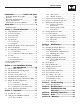
Table of Contents Guardian Air-cooled 7 kW, 12 kW and 15 kW Generators Introduction ........................Inside Front Cover 3.2.2 “Off” Position ....................................14 Read This Manual Thoroughly ........................IFC Contents ..........................................................IFC Operation and Maintenance ............................IFC How to Obtain Service ....................................IFC Authorized Dealer Locator Number ....................IFC 3.2.
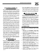
IMPORTANT SAFETY INSTRUCTIONS Guardian Air-cooled 7 kW, 12 kW and 15 kW Generators SAVE THESE INSTRUCTIONS – The manufacturer suggests that these rules for safe operation be copied and posted near the unit’s installation site. Safety should be stressed to all operators and potential operators of this equipment. ! ! WARNING: ! GENERAL HAZARDS ! ! The engine exhaust from this product contains chemicals known to the state of California to cause cancer, birth defects or other reproductive harm.
IMPORTANT SAFETY INSTRUCTIONS Guardian Air-cooled 7 kW, 12 kW and 15 kW Generators ELECTRICAL HAZARDS • All generators covered by this manual produce dangerous electrical voltages and can cause fatal electrical shock. Utility power delivers extremely high and dangerous voltages to the transfer switch as does the standby generator when it is in operation. Avoid contact with bare wires, terminals, connections, etc., while the unit is running.
Section 1 — General Information Guardian Air-cooled 7 kW, 12 kW and 15 kW Generators DANGER ! 1.1 Only qualified electricians or contractors should attempt such installations, which must comply strictly with applicable codes, standards and regulations. UNPACKING/INSPECTION After unpacking, carefully inspect the contents for damage. • This standby generator set has been factory supplied with a weather protective enclosure that is intended for outdoor installation only. 1.
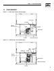
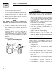
Section 1 — General Information Guardian Air-cooled 7 kW, 12 kW and 15 kW Generators 1.4 YOUR GENERATOR Figure 1.1 – 7 kW, Single Cylinder GH-410 Engine Control Panel Data Decal Exhaust Enclosure Air Filter Fuel Regulator Oil Filter Battery Compartment Figure 1.
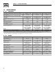
Section 1 — General Information Guardian Air-cooled 7 kW, 12 kW and 15 kW Generators 1.5 SPECIFICATIONS 1.5.1 GENERATOR Rated Max. Continuous Power Capacity (Watts*) Rated Voltage Rated Max.
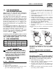
Section 1 — General Information Guardian Air-cooled 7 kW, 12 kW and 15 kW Generators 1.6 FUEL REQUIREMENTS AND RECOMMENDATIONS With LP gas, use only the vapor withdrawal system. This type of system uses the vapors formed above the liquid fuel in the storage tank. The engine has been fitted with a fuel carburetion system that meets the specifications of the 1997 California Air Resources Board for tamper-proof dual fuel systems.
Section 1 — General Information Guardian Air-cooled 7 kW, 12 kW and 15 kW Generators 5. Remove the small brass hose fitting from the idle circuit port of the regulator housing. 6. Remove the small jet (0D5698A) located in the side of the regulator housing and install it into the small threaded hole in the idle circuit port on the regulator. 7. Refit the brass hose fitting to the idle circuit port of the regulator. Use pipe thread sealant to reseal the threads on the hose fitting. 8.
Section 1 — General Information Guardian Air-cooled 7 kW, 12 kW and 15 kW Generators NOTE: 1.10 BATTERY INSTALLATION Fill the battery with the proper electrolyte fluid if necessary and have the battery fully charged before installing it. Before installing and connecting the battery, complete the following steps: 1. Set the generator's Auto/Off/Manual switch to OFF. 2. Turn off utility power supply to the transfer switch. 3. Remove the 5 amp and 15 amp fuses from the generator control panel.
Section 2 — Post Installation Start-up and Adjustments Guardian Air-cooled 7 kW, 12 kW and 15 kW Generators The following procedures are to be observed: • Wear full eye protection and protective clothing; • Where electrolyte contacts the skin, wash it off immediately with water; • Where electrolyte contacts the eyes, immediately flush thoroughly with water and seek medical attention; and • Spilled electrolyte is to be washed down with an acid neutralizing agent.
Section 2 — Post Installation Start-up and Adjustments Guardian Air-cooled 7 kW, 12 kW and 15 kW Generators 8. Connect an accurate AC voltmeter and a frequency meter across transfer switch terminal lugs E1 and E2. Voltage should be 242-252 volts; frequency should read about 61-63 Hertz. 9. Connect the AC voltmeter test leads across terminal lug E1 and neutral; then across E2 and neutral. In both cases, voltage reading should be 121126 volts AC. 10.
Section 3 — Operation Guardian Air-cooled 7 kW, 12 kW and 15 kW Generators 2.6 ADJUSTING THE REGULATOR (NATURAL GAS ONLY) Figure 2.2 — Placement of Regulator Although the generator has been factory set to provide maximum power, it may be necessary in some areas to adjust this setting. Because natural gas has different BTU or power content across the country the engine may not perform as designed. If you experience engine problems at high or full load conditions follow these steps.
Section 3 — Operation Guardian Air-cooled 7 kW, 12 kW and 15 kW Generators Figure 2.3 — Engine Governor Adjustment ◆ 2.7.3 ADDITIONAL CORROSION PROTECTION Periodically spray all engine linkage parts and brackets with corrosion inhibiting spray such as WD-40 or a comparable product. Idle Spring 2.8 Governor Shaft (Rotate Clockwise) VOLTAGE REGULATOR ADJUSTMENT With the frequency between 62-63.5 Hertz, slowly turn the slotted potentiometer (Figure 2.5) until line voltage reads 244-252 volts.
Section 3 — Operation Guardian Air-cooled 7 kW, 12 kW and 15 kW Generators 8. Turn ON the utility power supply to the transfer switch, which will allow the transfer switch to transfer back to utility power. The unit will continue to run for one minute and then shut down. 9. Allow the unit to cool. 10. Drain the oil and remove the oil filter. Replace the oil filter according to Section 4.4, “Changing the Oil Filter” (Page 18). Replace the oil with synthetic oil as recommended in Section 4.
Section 3 — Operation Guardian Air-cooled 7 kW, 12 kW and 15 kW Generators D.Utility Voltage Pickup Sensor • This sensor monitors utility power supply voltage. When that voltage is restored to above 70 percent of the nominal source voltage, a retransfer time delay starts timing. E.Retransfer Time Delay • This timer runs for about 15 seconds. • At end of a 15-second delay, circuit board action de-energizes the transfer relay in the transfer switch. • Retransfer to utility power source then occurs. F.
Section 3 — Operation Guardian Air-cooled 7 kW, 12 kW and 15 kW Generators 3.6 SETTING THE EXERCISE TIMER Figure 3.3 – Low Oil Pressure and High Temperature Switches Your generator is equipped with an exercise timer. Once it is set, the generator will start and exercise once every seven days, on the day of the week and at the time of day you complete the following sequence. During this exercise period, the unit runs for approximately 12 minutes and then shuts down.
Section 4 — Maintenance Guardian Air-cooled 7 kW, 12 kW and 15 kW Generators 4.1 FUSE Figure 4.2 — Oil Dipstick and Fill, 7 kW The generator panel’s 15 amp fuse (Figure 4.1) protects the DC control circuit against overload. The fuse is wired in series with the battery output lead to the panel. If the fuse element has melted open, you cannot crank or start the engine. You should replace the fuse using only an identical 15-amp replacement.
Section 4 — Maintenance Guardian Air-cooled 7 kW, 12 kW and 15 kW Generators 4.3.2 OIL CHANGE PROCEDURE To change the oil, proceed as follows: 1. Run the engine until it is thoroughly warmed up then shut OFF the engine. 2. Immediately after the engine shuts OFF, pull the oil drain hose (Figure 4.4) free of its retaining clip. Remove the cap from the hose and drain the oil into a suitable container. Figure 4.4 – Oil Drain Hose and Filter Loos en Oil Drain Hose 4.
Section 4 — Maintenance Guardian Air-cooled 7 kW, 12 kW and 15 kW Generators 4.6 SPARK PLUG(S) Reset the spark plug(s) gap or replace the spark plug(s) as necessary. See Section 4.13 (Page 22) for maintenance requirements. 1. Clean the area around the base of the spark plug(s) to keep dirt and debris out of the engine. Clean by scraping or washing using a wire brush and commercial solvent. Do not blast the spark plug(s) to clean. 2. Remove the spark plug(s) and check the condition.
Section 4 — Maintenance Guardian Air-cooled 7 kW, 12 kW and 15 kW Generators 4.8 ADJUSTING VALVE CLEARANCE After the first 50 hours of operation, you should adjust the valve clearance in the engine. Important: If you feel uncomfortable about doing this procedure or you don't have the proper tools, please contact your Generac Authorized dealer for service assistance. This is a very important step to insure longest life for your engine.
Section 4 — Maintenance Guardian Air-cooled 7 kW, 12 kW and 15 kW Generators 4.10 ATTENTION AFTER SUBMERSION 4.12.2 RETURN TO SERVICE If the generator has been submerged in water, it MUST NOT be started and operated. Following any submersion in water, have a Generac Authorized Dealer thoroughly clean and dry the generator. To return the unit to service after storage, proceed as follows: 4.11 CORROSION PROTECTION Periodically wash and wax the enclosure using automotive type products.
Section 4 — Maintenance Guardian Air-cooled 7 kW, 12 kW and 15 kW Generators 4.13 SERVICE SCHEDULE ATTENTION: It is recommended that all service work be performed by your nearest Generac Authorized Dealer. SYSTEM/COMPONENT X = Action R = Replace as Necessary * = Notify Dealer if Repair is Needed.
Section 5 — Troubleshooting Guardian Air-cooled 7 kW, 12 kW and 15 kW Generators 5.1 TROUBLESHOOTING GUIDE PROBLEM CAUSE The engine will not crank. 1. Fuse blown 1. Replace 15A fuse on generator control panel. 2. Loose, corroded or defective 2. Tighten, clean or replace battery cables as necessary. 3. Defective starter contactor (7 kW) 3. * 4. Defective starter motor 4. * 5. Dead Battery 5. Charge or replace battery. The engine cranks but will not start. 1. Out of fuel 2.
Section 6 — Electrical Data Guardian Air-cooled 7 kW, 12 kW and 15 kW Generators Wiring Diagram – 12 & 15 kW – Drawing No.
Section 6 — Electrical Data Guardian Air-cooled 7 kW, 12 kW and 15 kW Generators Wiring Diagram – 12 & 15 kW – Drawing No.
Section 6 — Electrical Data Guardian Air-cooled 7 kW, 12 kW and 15 kW Generators Electrical Schematic – 12 & 15 kW – Drawing No.
Section 6 — Electrical Data Guardian Air-cooled 7 kW, 12 kW and 15 kW Generators Electrical Schematic – 12 & 15 kW – Drawing No.
Section 6 — Electrical Data Guardian Air-cooled 7 kW, 12 kW and 15 kW Generators Wiring Diagram – 7 kW – Drawing No.
Section 6 — Electrical Data Guardian Air-cooled 7 kW, 12 kW and 15 kW Generators Wiring Diagram – 7 kW – Drawing No.
Section 6 — Electrical Data Guardian Air-cooled 7 kW, 12 kW and 15 kW Generators Electrical Schematic – 7 kW – Drawing No.
Section 6 — Electrical Data Guardian Air-cooled 7 kW, 12 kW and 15 kW Generators Electrical Schematic – 7 kW – Drawing No.
Section 7 — Exploded Views and Parts Lists Guardian Air-cooled 7 kW, 12 kW and 15 kW Generators Enclosure – Drawing No.
Section 7 — Exploded Views and Parts Lists Guardian Air-cooled 7 kW, 12 kW and 15 kW Generators Enclosure – Drawing No. 0D3416-K ITEM 1 PART NO. QTY.
Section 7 — Exploded Views and Parts Lists 29 28 36 31 30 39 35 3 17 13 17 4 19 45 44 47 27 0 38 37 7 22 46 14 15 2 48 29 28 35 6 38 7 16 23 27 8 32 8,9 34 5 15 14 34 23 16 12 3 40 20 49 43 13 45 44 42 1 41 11 14 47 45 24 45 31 47 Guardian Air-cooled 7 kW, 12 kW and 15 kW Generators Control Panel – Drawing No.
Section 7 — Exploded Views and Parts Lists Guardian Air-cooled 7 kW, 12 kW and 15 kW Generators Control Panel – Drawing No. 0D8503-E ITEM PART NO. QTY.
Section 7 — Exploded Views and Parts Lists Guardian Air-cooled 7 kW, 12 kW and 15 kW Generators GT-990 Engine – Drawing No.
Section 7 — Exploded Views and Parts Lists Guardian Air-cooled 7 kW, 12 kW and 15 kW Generators GT-990 Engine – Drawing No. 0D8674-C Part 1 ITEM PART NO. QTY.
Section 7 — Exploded Views and Parts Lists Guardian Air-cooled 7 kW, 12 kW and 15 kW Generators GT-990/760 Engine – Drawing No.
Section 7 — Exploded Views and Parts Lists Guardian Air-cooled 7 kW, 12 kW and 15 kW Generators GT-990/760 Engine – Drawing No. 0D8674-C Part 2 ITEM PART NO. QTY.
Section 7 — Exploded Views and Parts Lists Guardian Air-cooled 7 kW, 12 kW and 15 kW Generators 7 kW Generator – Drawing No.
Section 7 — Exploded Views and Parts Lists Guardian Air-cooled 7 kW, 12 kW and 15 kW Generators 7 kW Generator – Drawing No. 0D3504-B ITEM PART NO. QTY.
Section 7 — Exploded Views and Parts Lists 28 27 28 17 32 31 28 13 11 2 5 24 38 7 21 34 12 33 39 6 8 4 9 31 37 40 38 3 20 14 2 22 15 1 19 10 17 10 19 32 30 25 24 16 26 29 35 18 36 29 10 41 31 32 42 41 Guardian Air-cooled 7 kW, 12 kW and 15 kW Generators 12 kW and 15 kW Generator – Drawing No.
Section 7 — Exploded Views and Parts Lists Guardian Air-cooled 7 kW, 12 kW and 15 kW Generators 12 kW and 15 kW Generator – Drawing No. 0D3417-B ITEM 1 2 3 4 5 6 7 8 9 10 11 12 13 14 15 16 17 18 19 20 21 22 23 24 25 26 27 28 29 30 31 32 33 34 35 36 37 38 39 40 41 42 PART NO. QTY.
Section 7 — Exploded Views and Parts Lists 42 10 17 50 31 25 28 27 37 24 35 36 23 44 33 45 43 39 19 18 20 34 46 11 32 22 48 47 26 41 38 29 30 25 12 51 40 21 13 14 15 53 49 1 6 54 16 52 1 2 5 4 3 7 11 8 9 Guardian Air-cooled 7 kW, 12 kW and 15 kW Generators GN410 Engine – Drawing No.
Section 7 — Exploded Views and Parts Lists Guardian Air-cooled 7 kW, 12 kW and 15 kW Generators GN410 Engine – Drawing No. 0D3539-B Part 1 ITEM PART NO. QTY.
Section 7 — Exploded Views and Parts Lists 27 24 5 23 46 6 13 7 20 6 6 21 42 43 44 22 41 3 40 39 6 29 15 18 19 17 16 14 8 9 30 32 25 31 6 11 10 12 28 33 26 1 36 35 18 18 35 34 2 37 38 4 6 Guardian Air-cooled 7 kW, 12 kW and 15 kW Generators GN410 Engine – Drawing No.
Section 7 — Exploded Views and Parts Lists Guardian Air-cooled 7 kW, 12 kW and 15 kW Generators GN410 Engine – Drawing No. 0D3539-B Part 2 ITEM PART NO. QTY.
Section 7 — Exploded Views and Parts Lists 21 25 24 22 23 29 18 17 6 13 26 48 11 10 32 28 12 20 21 25 24 9 23 22 19 17 12 28 10 15 14 27 31 3 11 4 2 5 16 29 18 7 8 1 26 37 15 14 13 16 32 19 35 33 10 34 FOR GT 760 ENGINE ONLY 20 37 36 Guardian Air-cooled 7 kW, 12 kW and 15 kW Generators Gas Regulator – Drawing No.
Section 7 — Exploded Views and Parts Lists Guardian Air-cooled 7 kW, 12 kW and 15 kW Generators Gas Regulator – Drawing No. 0D8720-B ITEM 1 2 3 4 5 6 7 8 9 10 11 12 13 14 15 16 17 18 19 20 21 22 23 24 25 26 27 28 29 30 31 32 33 34 35 36 37 PART NO.
50 716 [28 743 [29 M6PEM M6P M6PEM-T PE T LEFT SIDE VIEW 622 [24.5"] 604 [23.5"] 76.2mm [3.00"] PEA GRAVEL MINUMUM 704 [27.7"] 207 [8.14"] TRANSFER SWITCH (IF SUPPLIED) 308 [12"] FRONT VIEW 1232 [48.5"] 1193 [47"] "DO NOT LIFT BY THE ROOF" LIFTING HOLES 4-CORNERS Ø30.2mm [Ø1.19"] 149 [5.9"] RIGHT SIDE VIEW 490.7 [ AIR 260 [10.2"] **ALL DIMENSIONS IN: MILLIMETERS [INCHES] REAR VIEW ROUNDING LUG CABLE ACCESS HOLES.
Section 9 — Notes Guardian Air-cooled 7 kW, 12 kW and 15 kW Generators 51
Section 10 – Warranty Guardian Air-cooled 7 kW, 12 kW and 15 kW Generators NOTE: This Emission Control Warranty Statement pertains to this product only IF the generator size is 15 kW or below. CALIFORNIA AND FEDERAL EMISSION CONTROL WARRANTY STATEMENT YOUR WARRANTY RIGHTS AND OBLIGATIONS The California Air Resources Board (CARB) and the United States Environmental Protection Agency (EPA), together with Generac Power Systems, Inc.
Section 10 – Warranty Guardian Air-cooled 7 kW, 12 kW and 15 kW Generators EMISSION CONTROL SYSTEM WARRANTY Emission Control System Warranty (ECS Warranty) for 1997 and later model year engines: (a) Applicability: This warranty shall apply to 1997 and later model year engines. The ECS Warranty Period shall begin on the date the new engine or equipment is purchased by/delivered to its original, end-use purchaser/owner and shall continue for 24 consecutive months thereafter.
Section 10 – Warranty Guardian Air-cooled 7 kW, 12 kW and 15 kW Generators GENERAC POWER SYSTEMS STANDARD "TWO YEAR" LIMITED WARRANTY FOR GUARDIAN “EMERGENCY AUTOMATIC STANDBY GENERATORS” For a period of two years from the date of original sale, Generac Power Systems, Inc.