® Owner’s Manual Power Zone® Connectivity Server SAVE THIS MANUAL FOR FUTURE REFERENCE
WARNING CANCER AND REPRODUCTIVE HARM www.P65Warnings.ca.gov.
Table of Contents Section 1: Introduction and Safety Introduction ..................................................................1 Read This Manual Thoroughly ....................................1 Safety Rules .................................................................1 General Hazards .........................................................2 Electrical Hazards .......................................................2 Section 2: General Information Equipment Description ...........................
This page intentionally left blank.
Introduction and Safety Section 1 Introduction and Safety Introduction Thank you for purchasing a Generac Power Systems, Inc. product. This unit has been designed to provide high performance, efficient operation and years of use when maintained properly. The information in this manual is accurate based on products produced at the time of publication. The manufacturer reserves the right to make technical updates, corrections, and product revisions at any time without notice.
Introduction and Safety Electrical Hazards DANGER Indicates a hazardous situation which, if not avoided, will result in death or serious injury. (000001) WARNING Indicates a hazardous situation which, if not avoided, could result in death or serious injury. (000002) CAUTION DANGER Electrocution. Contact with bare wires, terminals, and connections while generator is running will result in death or serious injury. (000144) DANGER Electrocution.
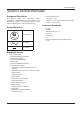
General Information Section 2 General Information Equipment Description The Generac Power Zone Connectivity Server (Assembly No. 10000039844) is a user interface for the Power Zone system. The Connectivity Server can be used in applications other than generator control. – Ethernet – 1 Port – RS-485 – 1 Port for Generator Main Controller – USB – 1 Type A (Host) Codes and Standards Symbol Definition G • Communications Ports AC Generator • UL 2200 • UL6200 • CSA STD C22.2 No.
General Information Specifications Environmental Specifications Operating Temperature Humidity Sealing Enclosure Weight Power Supply Requirements Power Supply Voltage Power Supply Usage Power Supply Cable Communication (Ethernet) Number of Ports Communication Link Communication Cable Maximum Cable Length Baud Rate Auto-Detect Communication (RS-485) Number of Ports Communication Link Communication Cable Maximum Cable Length Baud Rate Maximum Number of Devices Protocol/Device Type Communication (USB) Number
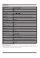
General Information Connection Locations D C B A 009515 Figure 2-1. Connection Locations (Bottom View) A Ethernet Connection C USB Connection B Power and RS-485 Connection (PWR_RS485 Connector) D HDMI Connection B A 010080 Figure 2-2. LED Locations (Front View) A Power LED (Red) B Communication LED (Green) NOTE: See Connection Details for more information regarding the connections and LEDs.
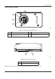
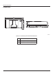
General Information Dimensions A B C 009516 Figure 2-3. Connectivity Server Enclosure Dimensions 6 A 6.02 in (152.9 mm) ± 0.01 in (0.3 mm) B 3.37 in (85.5 mm) ± 0.01 in (0.3 mm) C 1.65 in (42.0 mm) ± 0.01 in (0.
Installation and Operation Section 3 Installation and Operation Installation WARNING Equipment damage. Only qualified service personnel may install, operate, and maintain this equipment. Failure to follow proper installation requirements could result in death, serious injury, and equipment or property damage. (000182a) The Connectivity Server is installed using a conduit connector (part no. 10000032818). See Figure 3-1.
Installation and Operation Connection Details Connector Description PWR_RS485-5 12 V PWR_RS485-4 Ground PWR_RS485-3 RS-485 Ground PWR_RS485-2 RS-485 - PWR_RS485-1 RS-485 + Purpose Wire # (Default) 15F Provides power to the Connectivity Server 0C 0B This is Modbus Master and is used to connect to Power Zone Pro Main Controller 393 392 HDMI High-Definition Multimedia Device connector For Generac Engineering Use Only – Ethernet RJ-45 Ethernet connector Used to connect to PC, BMS or oth
Installation and Operation Ethernet Connection 1. i % See Figure 3-3. To connect via Ethernet, the Ethernet IP Address is required. This information can be accessed via the Power Zone Pro Main Controller “System Details” menu and by selecting “Network Info” (C). NOTE: The IP address and subnet mask on your PC's Ethernet port must be set to a fixed IP address in the same subnet range as the IP address of the connectivity server. /kWh 2. Connect Ethernet cable from the Connectivity Server to the PC.
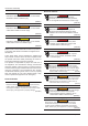
Installation and Operation Screen Layout See Figure 3-5. The screen is divided into the Top Banner (A), the Bottom Banner (B), and the main screen information area in the center (C). The top and bottom banners are displayed on every screen. A C B 007514 Figure 3-5. Screen Layout Top Banner A B C D 007516 Figure 3-6. Top Banner Features (A) Keyswitch Status A red LED indicates the key is in the OFF position. A green LED indicates the key is in the AUTOMATIC position.
Installation and Operation Bottom Banner the bottom of the screen. The icons are always visible and include a BACK icon to navigate back to the top layer. Hovering the mouse over the icon will display a “tool tip” above the icon describing its function. See Figure 3-8. All of the displays and features of Power Zone are accessed via a nested menu system. Navigation is performed by selecting the relevant icon at A B D C F E G H J 007517 Figure 3-8.
Installation and Operation Home Screen Bargraphs See Figure 3-9. The center of the screen contains data in the form of bargraphs. The bargraphs contain markers (A) that represent the trigger points for alarms and warnings. The markers are white lines. The color of the bar changes to yellow once the measurement triggers a warning (either high or low). The color of the bar changes to red once the measurement triggers an alarm. If a measured value exceeds the bargraph range, the bargraph is outlined in red.
Installation and Operation 007522 Figure 3-12. Language Selection Units of Measure To set the units of measure go to the (E) Setup icon and choose “User”. A selection for “Units of Measure” will appear on the right side of the screen. Checking the “Save” button will save the selection. Checking the “Set As Default” will apply the selection to the Built-in Display and all new remote users. 009630 Figure 3-14. Date/Time Health Checkmark See Figure 3-15. The checkmark indicates the system is healthy.
Installation and Operation 007525 Figure 3-16. Shutdown Alarm Condition (Red) 007528 Figure 3-19. Numeric Value Editing (with ranges) 007526 Figure 3-17. Non-Shutdown Alarm Condition (Red) 007526 Figure 3-18. Warning Condition (Yellow) Editing Editing of configuration parameter values is performed by two methods: by entering a value (Figure 3-19) or selecting a value using the pull down selection box (Figure 3-20). 007529 Figure 3-20.
Installation and Operation Screen Icon Details Home Screen This screen displays bar graphs for the most common measurements, and an overall health check for the generator. The number of displayed measurements will change depending on whether or not the generator is running. 007532 Figure 3-23. Maintenance Notes System Dashboard Screen Engine Detail Screen See Figure 3-21. This screen displays bargraphs for the most common measurements.
Installation and Operation System Detail Menu The System Detail menu provides access to the alarm history, event history, shutdown bypass alarm log, run times, maintenance remaining, nameplate data, dealer information, system notes and utility screens. Alarms and Warnings 007534 Figure 3-25. Engine Settings Alternator Detail Screen See Figure 3-26. The Alternator Detail Screen displays bargraphs of measured alternator parameters.
Installation and Operation Press the “Reset All” button (B) to clear all active alarms and warnings. If the conditions for an alarm or warning are still present, they will reappear as new. NOTE: Resetting all alarms can result in the generator restarting if all other start conditions are active. Press the “Sort” button (C) to list the alarms and warnings from newest to oldest, or from oldest to newest. C B A 007734 Figure 3-30. Alarm History Shutdown Bypass Alarms 010147 Figure 3-29.
Installation and Operation 007537 Figure 3-33. Maintenance Remaining 009631 Figure 3-31. Shutdown Bypass Alarms Run Times See Figure 3-32. The Run Times screen shows the generator operation history. Nameplate Data See Figure 3-34. The Nameplate Data screen displays generator information such as Generator model, Production Date, Country of Origin, kW rating and voltage. 007536 Figure 3-32. Run Times 007538 Maintenance Remaining See Figure 3-33.
Installation and Operation Dealer Information See Figure 3-35. The Dealer Information screen is an editable text field where dealer contact information is stored. 007541 Figure 3-37. System Setup Wiring type indicates single or three-phase generator wiring. 007539 Switch type defines the type of generator output switch or breaker used. The options are: Figure 3-35. Dealer Information System Notes The System Notes screen is an editable text field where system notes and information are stored.
Installation and Operation • Analog Pressure Loss Delay: The amount of time (in seconds) from the last good sensor value before the pressure sensor value is considered lost. B A A B 009711 Figure 3-40. Setup Channel 009709 Figure 3-38. Dual Fuel Settings See Figure 3-39. Select the dropdown to choose which sensor(s), if any, are attached to the generator. Select “Disabled” if there are no sensors attached. Air/Fuel Setup See Figure 3-41.
Installation and Operation Auto Mains Failure (AMF) See Figure 3-42. Auto Mains Failure (AMF) provides a way to control a non-intelligent transfer switch from the Power Zone Pro Main Controller. When AMF is enabled, the Controller monitors utility voltage and frequency, controls starting and stopping of the generator, and controls switching of the load from utility to generator and back again as needed. See Table 1 for a description of each parameter. To set the configuration: 1.
Installation and Operation Table 1 - AMF Parameters Load Accept Voltage Volts, 85% - 95% of target voltage The minimum voltage the generator must provide before switching the load to generator. Load Accept Frequency Hz, 85% - 95% of target frequency The minimum frequency the generator must provide before switching the load to generator. Warm Up Time Seconds, 0 - 1200 Amount of time after the generator reaches load accept voltage and frequency before switching the load to generator.
Installation and Operation means the alarm condition is only evaluated after a hold off timer has expired after the generator started running. Protections (Alarms, Event History, GFI, I2T) See Figure 3-45. The Protections screen is used to set custom alarms and warnings or edit existing alarms and warnings for most of the measured values in the system. The events can be logged or emailed.
Installation and Operation hold off timer has expired after the generator started running. 5. Enter the setpoint value in the units of measure (F). A 6. Check either greater than (GT), or less than (LT) (G). B 7. Enter a delay time (H). This is the amount of time the alarm condition must be active before it is set. 8. C Select “Apply Changes” to save the settings. D A E B C F 010227 Figure 3-48. Sensor Fault Setup D E Event History Setup F See Figure 3-49.
Installation and Operation I2T Enabled The i2t algorithm monitors the maximum output current on all legs of the alternator and integrates the square of the maximum current with respect to time. When this feature is enabled and the integral reaches the normalized value of “90”, a shutdown fault is triggered. When this feature is not enabled, the current is not monitored in this way. Examples: • 3 x rated current for 10 seconds is 32 x 10 = 90 • 1.1 x rated current for 74 seconds is 1.
Installation and Operation Maintenance Setup Modules See Figure 3-54. This screen is used to setup maintenance intervals for the generator. Intervals can be set to different units as appropriate for the equipment. To set a maintenance interval, select the equipment of choice. See Figure 3-56. This screen allows you to select which module you wish to setup. The Automatic Voltage Regulator (AVR) and Governor are covered by the Alternator setup section and the Engine setup section. 007555 Figure 3-56.
Installation and Operation NOTE: Pressing the “Defaults” button will erase all current relay selections and they will all need to be entered again. Digital I/O Digital inputs are automatically mapped to certain places and used within the program. Further custom mapping such as an input to an output can be performed by the user as desired. Mapping is performed by channel numbers. Digital Outputs and Digital Output Functions follow a similar concept with Channels and Function names.
Installation and Operation Analog I/O Analog I/O is based on the similar Channels and Functions system used by the Digital I/O. Analog inputs usually come preprogrammed from the factory. An analog input (to the program) can be a real physical analog input or it can be a computed (or derived) input. For example, kW can be an analog input to the program, but it is computed (derived) based on multiple measurements, not read from an input pin.
Installation and Operation Table 2 - Time Constants on Filters Filter Setting Time Constant (ms) 0 No filter 1 No filter 2 14 3 15 4 16 5 18 6 20 7 23 8 27 9 34 10 48 11 90 the analog output pin where channel IDs 1-2 are analog voltage and 3-9 are PWM pins. 2. Select the source type (A) as analog or control. A different pick list will be displayed for each. 3. Select the function code (B) from the pick list. 4. Scale the output (C).
Installation and Operation represents a 100% duty cycle. The output duty cycle is the analog or control value divided by the PWM counts value. In this example, a control value of 33 divided by the PWM counts of 100 would result in a 33% duty cycle. 6. The Computed PWM Frequency (G) will be displayed. 7. Check the “Enable” checkbox (H) to enable the output. 8. Check the “Invert” checkbox (I) to invert the signal if required. For example, if the duty cycle is 75% it will change to 25%.
Installation and Operation existing client mode connection, the SSID of the most recently connected Wi-Fi network will be displayed following the text "Current saved profile". 1. See Figure 3-68. Click the “Manually Enter Wi-Fi” checkbox (A). 2. Enter SSID (Service Set Identifier) (B). 2. Select “Country Code” (B) to match the country the Client mode will be present in. 3. Enter network password (C) as required by network configuration. 3. Click the drop down menu for Channel ID (C). 4.
Installation and Operation Click “Apply Changes” (H) to place the Connectivity Server in Hotspot mode with the settings selected. 7. A Bluetooth Setup A network connection can be made between the Connectivity Server and a laptop, tablet, or smartphone using Bluetooth. The Power Zone Connectivity Server acts as the host and offers networking service to the connected device. With this connection, the web browser on the connected device can be used to view the Power Zone Application remotely.
Installation and Operation 2. The connection can be initiated in two ways: – Left mouse click on the menu item “Connect using” ĺ “Access Point” (B). – Right mouse click on the device that represents the Connectivity Server (A) and select “Connect using” ĺ “Access Point”. A B B A 009721 Figure 3-74. Change Bluetooth Name 3. Confirmation of name change is displayed. 4. See Figure 3-75. New name is now displayed in name text box (A). 009727 Figure 3-72. Initiate Connection 3.
Installation and Operation A A B B 009735 009733 Figure 3-77. Disconnect Bluetooth Figure 3-76. Disconnect from Paired Bluetooth Device 3. A confirmation message will be displayed once disconnected. 4. The device will no longer be displayed in the list of “Paired Devices”. Disconnect Network Connection to Connectivity Server Performing a disconnect from the paired device will break the network connection between the two devices.
Installation and Operation A B C D E F G H I J 007585 010392 Figure 3-78. Email Screen Figure 3-79. Configure Modbus Pass-through Configuring Modbus Pass-through Tools Menu See Figure 3-79. The Power Zone Connectivity Server acts as a gateway for external systems to exchange data with a Power Zone System using Modbus. The Connectivity Server supports both Modbus TCP and Modbus RTU over RS-485. See Figure 3-80.
Installation and Operation 3. The system will validate the credentials and, if successful, will allow access to the appropriate level of secured functionality. If the credentials were not valid a failure message will be shown. 3. To use a file stored on a USB device connected to the Connectivity Server, select the “Panel” tab and select “List Configuration Files”. Select the file and select “Load”. 009627 Figure 3-83. Write to Controller J1939 CAN Bus Diagnostics 009625 Figure 3-81.
Installation and Operation See Figure 3-86. The Clear Active button (A) will send a request to clear the Active DTC. If the condition which caused the DTC to appear is still present, the Active DTC entry will remain in the Active box. If the condition is no longer present, it will move into the Previously Active box. NOTE: Some DTCs will clear without the Clear Active button being pressed. The Clear Previously Active button (B) will clear the contents of the Previously Active section.
Installation and Operation Trending Power Zone has three ways to collect and analyze a series of values collected over a period of time: Remote Trending, Local Trending and Data Logging. Remote Trending See Figure 3-90. Remote Trending displays data in a graph as it is collected. Up to 16 values can be graphed at the same time. The values to be graphed are selected using the drop down lists on the left (A). The color of the drop down arrow indicates the color line that will be used to draw the graph.
Installation and Operation Local Trending Local Trending can be used to collect data at timed intervals as small as 0.1 ms. The data cannot be graphed until the data collection has stopped. The total amount of collected data cannot exceed 8,192 bytes. If trending 16 Bit data, the maximum number of points is 4,096. If trending 32 Bit data, the maximum number of data points is 2,048. The maximum number of data frames trended is the maximum number of data points divided by the number of parameters.
Installation and Operation data logging session can be configured and stored for later use. 1. See Figure 3-93. Select the New Logger button (A) to create a new logging session. 2. Select a data collection interval (B) to configure the logging session, set the duration of time for the data to be collected (C), and whether you want the data saved to the on-board storage of the Connectivity Server or to an external, USB connected storage device (D).
Installation and Operation Selecting the “Save” button (H) displays two buttons for remote users. One is to save the program locally. The other is to save the program to a USB drive. Remove a program by expanding the PLC slot and selecting the red button with the trash icon. G C D H B A E Figure 3-95. Load Software Package See Figure 3-96. Press the “Start” button (E) to begin the upgrade process.
Installation and Operation “Apply Changes” (F) for the certificates to be used. E F A 009623 D Figure 3-99. About Screen B Upload Documents Screen See Figure 3-100. The Upload Documents screen can be used to either provide translated Power Zone Owner’s Manuals or documentation like wiring diagrams for storage and use on the Connectivity Server. Only PDF files are currently supported. C To select a file from a mobile device: 1. Select “Local File” tab (A). 2. Select “Choose” (B).
Installation and Operation C A B D H E 009634 Figure 3-102. On-screen Keyboard F G 009624 Figure 3-100. Upload Documents Screen Login and Security See Figure 3-101. From the “Tools” menu (A), select “Login” (B). This screen provides a keyboard to input a password for access to restricted areas of the app. NOTE: If not logged in, the user will be prompted to enter a password if trying to access a restricted area of the app, as shown in Figure 3-102. B A 009633 Figure 3-101.
Installation and Operation This page intentionally left blank.
Troubleshooting Section 4 Troubleshooting Troubleshooting Guide Problem Solution Red LED in front of enclosure is OFF Verify 12 V power and ground wires are connected properly on PWR_RS485 connector to the Power Zone Pro Main Controller BS6 connector. Green LED in front of enclosure is OFF Verify the RS-485 wires are connected properly on PWR_RS485 connector to the Power Zone Pro Main Controller BS6 Connector.
Troubleshooting This page intentionally left blank.
® Part No. A0000007101 Rev. A 12/12/2019 ©2019 Generac Power Systems, Inc. All rights reserved. Specifications are subject to change without notice. No reproduction allowed in any form without prior written consent from Generac Power Systems, Inc. Generac Power Systems, Inc. S45 W29290 Hwy. 59 Waukesha, WI 53189 1-888-GENERAC (1-888-436-3722) www.generac.