
Owner's Manual


Owner’s Manual for Power Zone Connectivity Server 5
General Information
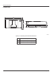
Connection Locations
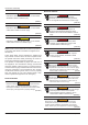
Figure 2-1. Connection Locations (Bottom View)
Figure 2-2. LED Locations (Front View)
NOTE: See Connection Details for more information regarding the connections and LEDs.
A Ethernet Connection C USB Connection
B
Power and RS-485 Connection
(PWR_RS485 Connector)
D HDMI Connection
A Power LED (Red)
B Communication LED (Green)
B
009515
D
C
A
B
010080
A